D flip-flop crossover circuit diagram
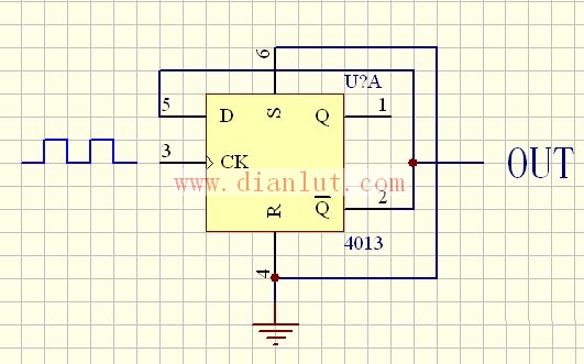
D flip-flop frequency dividing circuit
The figure shows the D flip-flop frequency dividing circuit. The 4013 in the circuit is a CMOS with a set-reset dual D flip-flop. D flip-flop works: SD and RD are connected to the input of the basic RS flip-flop, they are preset and clear, respectively, active low. When SD=1 and RD=0, regardless of the state of the input terminal D, Q=1, Q is non=0, that is, the trigger is set to 1; when SD=0 and RD=1, the state of the trigger is 0, SD and RD are also commonly referred to as direct set and set zero. We set them to have been added to a high level and do not affect the operation of the circuit.
cctv,cctv camera,outdoor,indoor,surveillance,home security
Dongguan Metalwork Technology Co., LTD. , https://www.dgdiecastpro.com