What is MDO? How does MDO work?
With the continuous development of science and technology, Xiao Bian just learned about the oscilloscope, and now there is a measuring artifact mixed domain oscilloscope. It seems that Xiao Bian really can not stop learning the pace of love it! Then go to the world of mixed domain oscilloscopes with your fans! Let us rise together knowledge...
What is MDO?
Before describing its internal technology, we should first understand what MDO is composed of.
In the past, analog, digital, and RF measurements required three different instruments:
â— Oscilloscope, used to time-correlate analog signals in the time domain
â— Logic analyzer for time-correlated measurements of digital signals in the time domain. Mixed signal oscilloscope (MSO) is an oscilloscope with digital channels added
Spectrum analyzer for measuring RF signals in the frequency domain
Mixed Domain Oscilloscope (MDO) is the first tool to integrate a mixed signal oscilloscope (including logic and protocol analysis functions) with a modern spectrum analyzer.
They have a complete set of input channels optimized for measuring analog, digital and RF signals:
â— 2 or 4 analog time domain channels, 100MHz, 200MHz, 350MHz, 500MHz or 1GHz bandwidth, with serial bus decoding and triggering
â— 16 digital time domain channels with a minimum timing resolution of 60.6ps, with serial bus decoding and triggering
â— 1 spectrum analyzer channel, up to 6GHz input frequency range
How does MDO work?
In order to provide these functions, especially RF measurement performance, the MDO uses a unique structure that may not be familiar to conventional spectrum analyzers or oscilloscope users.
The figure is a simplified block diagram of a conventional swept spectrum analyzer. The traditional structure is a swept superheterodyne spectrum analyzer (SA). It is this structure that allows engineers to perform frequency domain measurements decades ago.
The current generation of spectrum analyzers includes many digital elements such as ADCs, DSPs, and microprocessors. However, the basic frequency sweep method is still mostly the same.
The SA measures power versus frequency by downconverting the signal of interest and then sweeping the transmission band through the resolution bandwidth (RBW) filter. Behind the RBW filter is a detector that calculates the amplitude at each frequency point in the selected bandwidth.
The advantage of this method is that it provides a high dynamic range. The disadvantage is that only one frequency point of data can be calculated at a time. As a result, the measurement data is only valid for relatively stable, non-varying, narrow-band input signals.
The figure shows the structure of the vector signal analyzer VSA. The VSA represents a more modern spectrum analyzer architecture in which the local oscillator is stepped rather than scanned.
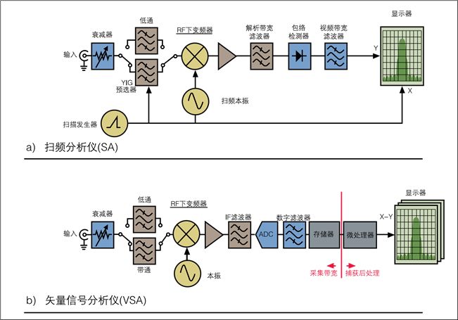
The resulting signal is filtered first, followed by analog-to-digital conversion. This results in a band-limited time domain signal that can be converted from the time domain to the frequency domain by using a DFT (Discrete Fourier Transform). Then use the resulting frequency domain information to draw a small portion of the spectrum picture on the picture around the local oscillator frequency.
Then the local oscillator steps to the next higher frequency and repeats this process until the entire spectrum is plotted. When dealing with time-varying RF, the stepper analyzer is better than the swept spectrum analyzer, but the prerequisite is that the bandwidth of interest is within the step width range, and the frequency-advance width is usually quite narrow (10MHz~25MHz).
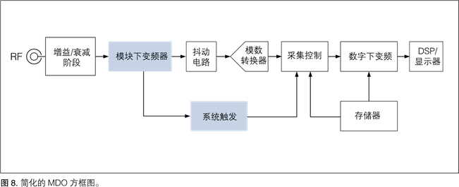
The figure is a simplified MDO block diagram. The highlighted module is only available in the MDO4000 series. What other modules are MDOMDO working on?
Behind the RBW filter is a detector that calculates the amplitude at each frequency point in the selected bandwidth. The advantage of this method is that it provides a high dynamic range. The disadvantage is that only one frequency point of data can be calculated at a time.
As a result, the measurement data is only valid for relatively stable, non-varying, narrow-band input signals. The figure shows the structure of the vector signal analyzer VSA. The VSA represents a more modern spectrum analyzer architecture in which the local oscillator is stepped rather than scanned.
The resulting signal is filtered first, followed by analog-to-digital conversion. This results in a band-limited time domain signal that can be converted from the time domain to the frequency domain by using a DFT (Discrete Fourier Transform). Then use the resulting frequency domain information to draw a small portion of the spectrum picture on the picture around the local oscillator frequency.
Then the local oscillator steps to the next higher frequency and repeats this process until the entire spectrum is plotted. When dealing with time-varying RF, the stepper analyzer is better than the swept spectrum analyzer, but the prerequisite is that the bandwidth of interest is within the step width range, and the frequency-advance width is usually quite narrow (10MHz~25MHz).
The figure is a simplified MDO block diagram. The highlighted module is only available in the MDO4000 series, while the other modules are common to the MDO4000 and MDO3000 series. Modern vector signal analyzers use basically the same structure.
The main difference between MDO and ordinary VSA is that MDO has:
â— ADC sampling rate is much higher, thus achieving ultra-wide capture bandwidth
â— The number of fixed down conversion ranges is small
The heart of MDO is the same analog-to-digital converter developed by Tektronix that is used in most Tektronix oscilloscopes. This 8-bit analog-to-digital converter samples at 10 GS/s and the input bandwidth exceeds 5 GHz.
In all MDOs, jitter is added to the signal to improve SFDR. After the data is collected into memory, hardware and software technologies are combined to perform digital down conversion (DDC), which greatly enhances signal fidelity.
This process accomplishes three things:
â— Data records are converted to I (in-phase) and Q (orthogonal) composite data formats
â— The center frequency is transmitted to DC, which can reduce the IQ sampling rate to half rate
â— Data is filtered and compressed to a sampling rate sufficient to cover the bandwidth
The digital signal processor in the MDO performs an FFT to convert the RF time domain data into frequency domain data in the form of a frequency spectrum. The entire spectrum is multiplied by the calibration factor to adjust the flatness and phase.
Then use a user-selectable detection method to determine how to compress a 1000-2,000,000 point FFT output to a wide 1,000 pixel display. It provides positive peaks, negative peaks, averages, and sample detectors.
Finally, the obtained spectrum is added to the logarithmic scale for display.
to sum up
Both MDO3000 and MDO4000 series can easily realize the functions of multiple instruments in one integrated platform.
The MDO4000 Series can display both time and frequency domains in a synchronized view and is particularly suitable for EMI debugging and integrated wireless transceivers.
Although using oscilloscope technology to build a high-fidelity spectrum analyzer has greatly exceeded the tradition, there are many technologies that can effectively achieve this goal, including:
â— Use dedicated spectrum analyzer input to improve fidelity
â— Use digital down converters and DFT technology to improve sensitivity with process gain
â— Using jitter to improve SFDR
â— Improve shielding
Using these techniques, MDOs achieve the fidelity required for spectral measurements while retaining the advantages offered by integrated oscilloscopes, including:
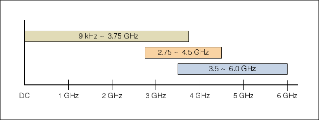
â— Wide capture bandwidth of at least 1 GHz at any center frequency, up to 3.75 GHz in some cases
â— Cost and space advantages, sharing a chassis, monitor, interface, power supply, etc.
â— Convenience of an integrated instrument
â— On the MDO4000 Series
- Analog channel and digital channel achieve time correlation
- Ability to view RF time domain data outside of the typical zero bandwidth provided by the spectrum analyzer
3U Splice Panel,3U Panel,3U Splice Panel Adapter,3U Splice Panel Bracket
Huizhou Fibercan Industrial Co.Ltd , https://www.fibercannetworks.com