Simple and easy to use wireless walkie-talkie solution analysis
First of all, someone asked me yesterday if I had a wireless walkie-talkie solution. This thing has a lot of basic online, analog, digital, as long as you want, just search for one. But the other party is a student. I want to do it myself in school. It is easy to do. This is not easy.
It’s not that things are not easy to get, but if there is no relevant foundation, no matter what the problem is, it is a fog. So I looked for it, there are a lot of programs, but there is no basis to get this basic will be depressed wall.....
But it is to find a fun thing, wireless microphone, simply say, you are talking with this thing, you can hear your voice on the radio. Put this first, then find something else and release it later.
Parameters: Frequency range: 88MHz-108MHz Operating voltage: 3V
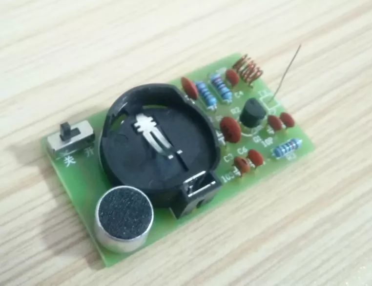
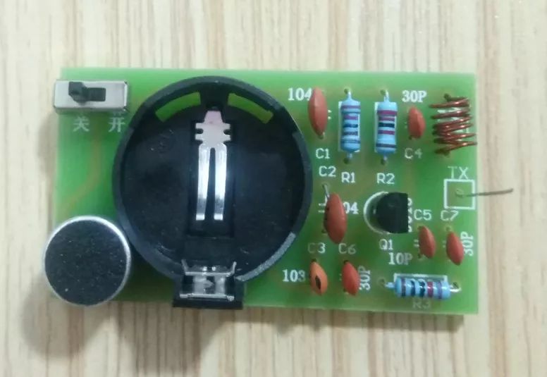
Circuit principle:
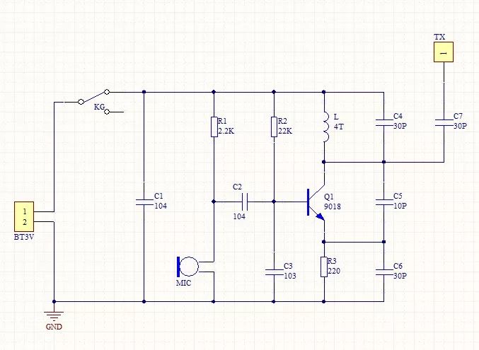
1. MIC is an electret microphone with positive and negative poles. Generally, the negative pole is connected to the outer casing. Its function is to induce the weak vibration of sound waves in the air and output the same electrical signals as the sound changes.
2. R1 is the bias resistor of the electret microphone MIC. With this resistor, the microphone can output the audio signal. This is because the MIC microphone itself has a primary FET amplification circuit to match the impedance and improve the output capability. The microphone does not need to be too sensitive, otherwise it will be easy to have acoustic feedback, resulting in self-excited howling.
3. C2 is an audio signal coupling capacitor that transmits the acoustic signal of the microphone sensing output to the next stage.
4.C3 is the base-level filter capacitor of transistor Q. On the one hand, it filters out high-frequency noise, on the other hand, the high-frequency potential of Q is 0. For high-frequency circuits above 50MHz, Q is a common-base amplifier circuit. This is the basis for the final oscillation, because the basic condition of the oscillating circuit is that it must have a certain gain, and then there is appropriate corresponding feedback, usually positive feedback.
5. R2 is the base-level bias resistor of transistor Q, which provides a smaller base current for Q, and Q will have a larger emitter-level current through R3. Due to the current in R2 and R3, voltage drops are generated on the respective resistors and interact with each other. As a result, the voltage is automatically stabilized in a certain value state. This is the emitter follower.
6. R3 is the emitter resistance of the transistor Q, which functions as a stable DC operating point and forms a high-frequency signal load resistor with C6, which is also part of the entire high-frequency oscillation circuit.
7. C4 and L form a parallel resonant circuit, which plays the role of adjusting the oscillation frequency. The capacity of C4, the diameter, spacing, number of turns of the coil L and the thickness of the enameled wire can be changed to change the transmission frequency.
8. C7 is a high-frequency signal output coupling capacitor, the purpose is to make the high-frequency signal into radio waves radiated into the sky. Therefore, the antenna is preferably vertically upward, preferably having a length equal to the wavelength or integer multiple of the radio wave frequency, and the perimeter should be wide and not blocked by metal objects. Description: The wavelength is equal to the reciprocal of the frequency, the frequency changes, and the wavelength also changes. The specific length of the antenna is also related to the output impedance and the antenna thickness. It is enough to connect a section of wire under the amateur line. If you want to find the farthest distance, you can do more of this. You can experiment with the technician and the launch distance can easily reach 50 meters.
9. C5 is a feedback capacitor and is a key component of the circuit's starting. When analyzing the high-frequency state of this circuit, the collector of the transistor Q is the output, the emitter is the input, and the output signal is applied to the input through C5, which produces a strong positive feedback, which naturally oscillates. This is the three-point oscillating circuit of the capacitor.
10. C1 is the power supply filter capacitor, which provides a loop for the AC signal and reduces the AC internal resistance of the power supply.
Debugging and installationAfter all the components have been soldered, the next work is mainly to debug the oscillation frequency: turn on a mobile phone or radio that can receive FM radio, then turn on the microphone power, hold the microphone, and blow or whisper to the microphone while facing the radio. Search the station until your voice is heard on the radio. If you still can't get your own sound in the whole frequency band (ie 88-108MHz), carefully use the non-inductive bamboo to move the spacing of the oscillating coil L. When you move, just pull or shrink the distance between each coil.
Since the numerical error of the electronic component may affect the transmission frequency, if the tension of the adjustment coil is still not effective, the L welding is increased by one turn or reduced by one, and the above adjustment is continued after re-welding. To increase the transmission distance, another wire is soldered at the TX as an antenna, and the specific length can be determined according to the effect at the time of debugging.
Note: The oscillating coil is an insulated enamel wire. When welding, use a blade to scrape off the insulating paint at the ends of the welding to weld. It can be wound around a line of water-based refills or water-based refills, initially 6 turns, the specific number of turns is determined according to commissioning.
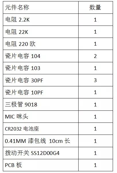
Component list:
Antenk battery holders for Cylindrical Cells
Thru Hole and Surface Mount or with Wire Leads
For A, AA, AAA, 1/2AA, CR2, CR123A, 1/3N,C, D, N, 12 Volt, 18350, 18650, 26650 Batteries
Antenk Battery Holders for Cylindrical Cells Type
Plastic Cost Effective Holders, Polyproplene base, coil spring contacts
PC Mountable and wire lead for on or off board applications
PC Connetcor for quick connection to automated board assemblies
Snap On Connector for off board connection using 9V connection
High Performance Leaf Spring Holders, High Temp. Nylon Base
SMT Holders, Gold plated contacts
THM Holders, Tin-Nickel Plated Contacts
Solder Lug Holders, for remote wiring applications
High Performance Coil Spring Holders, High Temp. Nylon Base
SMT Holders, Gold plated contacts
THM Holders, Tin-Nickel Plated Contacts
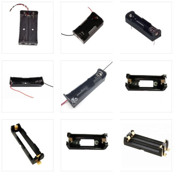
Battery Holder,Cylindrical Cell Holders,Cylindrical Battery Bracket,Custom Cylindrical Cell Holders,Battery Holders Cylindrical,18650 Battery Holders,alkaline batteries Holders
ShenZhen Antenk Electronics Co,Ltd , https://www.antenk.com