Electronic enthusiasts know 20 basic analog circuits
 The mastery of analog circuits is divided into three levels: the primary level: it is the skill to remember these twenty circuits, and the role of these twenty circuits. As long as it is an electronic enthusiast, as long as people who are learning automation, electronics and other electronic control professionals should be able to remember these twenty basic analog circuits.
Intermediate level: It is able to analyze the role of the key components in these 20 circuits, what is the influence of the function of the circuit when each component fails, the change rule of the parameters during measurement, and the handling method of the faulty component; Analyze the flow direction and phase change of the circuit signal; qualitatively analyze the change process of the signal waveform; qualitatively understand the magnitude of the input and output impedance of the circuit, and the relationship between the signal and the impedance. With this circuit knowledge, you are very likely to grow into an excellent service technician for electronics and industrial control equipment. The advanced level is to quantitatively calculate the input and output impedance of the twenty circuits, the ratio of the output signal to the input signal, the relationship between the signal current or voltage in the circuit and the circuit parameters, the amplitude and frequency relationship of the signal in the circuit, and the phase-frequency relationship. Characteristics, selection of component parameters in the circuit, etc. After reaching the advanced level, as long as you are willing, a respected high-paying career - the development and design engineer of electronic products and industrial control equipment will be your preferred career.
First, the bridge rectifier circuit
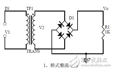
1. Unidirectional conductivity of the diode:
Voltammetric characteristic curve
Ideal switch model and constant voltage drop model
2. Bridge rectifier current flow process
Input and output waveform
3. Calculation: Vo, Io, diode reverse voltage.
Second, the power filter
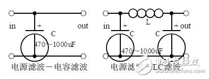
1. Process analysis of power supply filtering:
Waveform formation process:
2. Calculation: The capacity and withstand voltage value of the filter capacitor are selected.
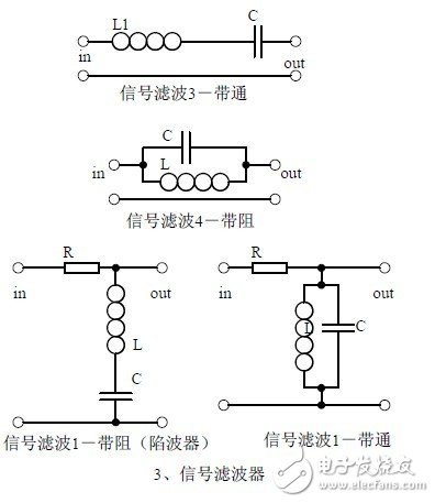
Third, the signal filter
1, the role of the signal filter:
The difference and the same point with the power filter:
2. Impedance calculation, amplitude-frequency relationship and phase-frequency relationship curve of LC series and parallel circuits.
3. Draw a passband curve.
Calculate the resonant frequency.
Fourth, the differential and integral circuit
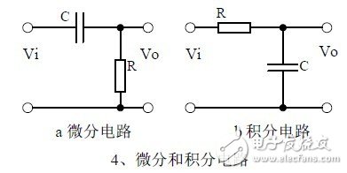
1, the role of the circuit, and the difference between the filter and the same point.
2. Analysis of the voltage change process of the differential and integral circuits, and draw a waveform diagram of the voltage change.
3. Calculation: time constant, voltage change equation, selection of resistance and capacitance parameters.
Five, common emitter amplification circuit
1. The structure of the triode, the current relationship of the poles of the triode, the characteristic curve, and the amplification condition.
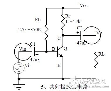
2, the role of components, the use of the circuit, voltage amplification, input and output signal voltage phase relationship, AC and DC equivalent circuit diagram.
3. Calculation of static working point and calculation of voltage amplification factor.
6. Voltage-divided bias common-emitter amplifier circuit
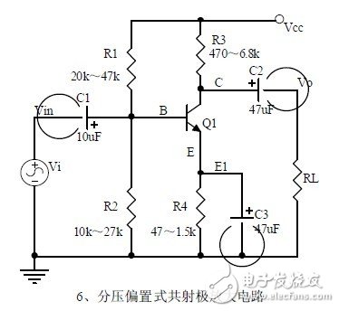
1, the role of components, the use of the circuit, voltage amplification, input and output signal voltage phase relationship, AC and DC equivalent circuit diagram.
2. Analysis of current series negative feedback process, negative feedback on circuit parameters.
3. Calculation of static working point and calculation of voltage amplification factor.
Seven, common collector amplifier circuit (emitter follower)
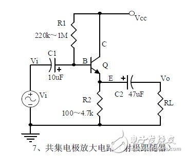
1, the role of components, the use of the circuit, voltage amplification, input and output signal voltage phase relationship, AC and DC equivalent circuit diagram. Input and output impedance of the circuit
Features.
2. Analysis of current series negative feedback process, negative feedback on circuit parameters.
3. Calculation of static working point and calculation of voltage amplification factor.
Eight, circuit feedback block diagram
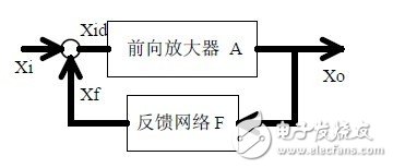
1. The concept of feedback, positive and negative feedback and its judgment method, parallel feedback and series feedback and its judgment method, current feedback and voltage feedback and its judgment method.
2. Amplification gain with a negative feedback circuit.
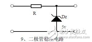
Nine, diode regulator circuit
Ten, series regulated power supply

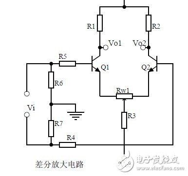
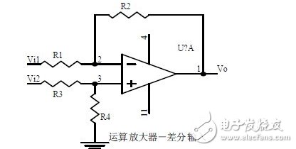
XI. Differential amplifier circuit
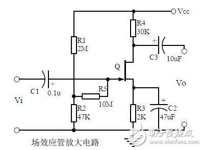
Twelve, FET amplification circuit
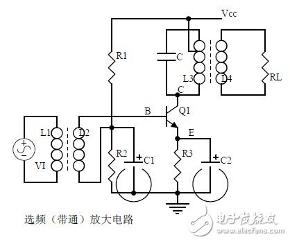
Thirteen, frequency selective (bandpass) amplifier circuit
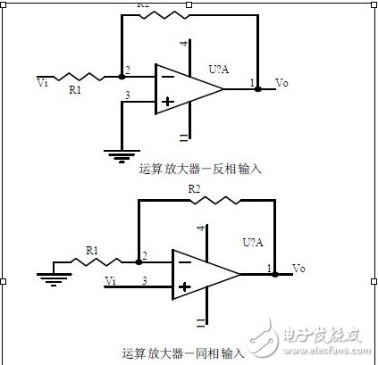
Fourteen, operational amplifier circuit
Fifteen, differential input operational amplifier circuit
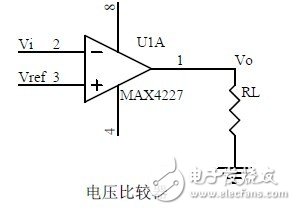
Sixteen, voltage comparison circuit
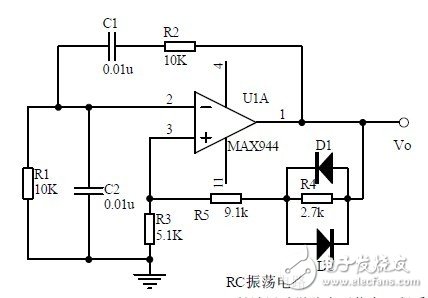
Seventeen, RC oscillator circuit
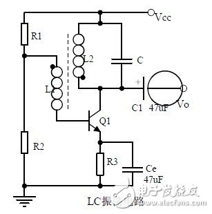
Eighteen, LC oscillator circuit
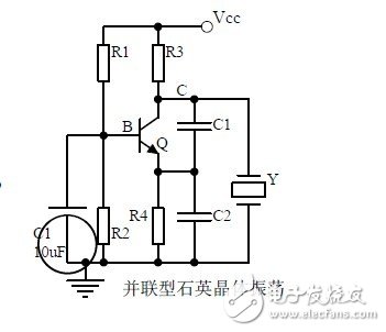
Nineteen, quartz crystal oscillator circuit
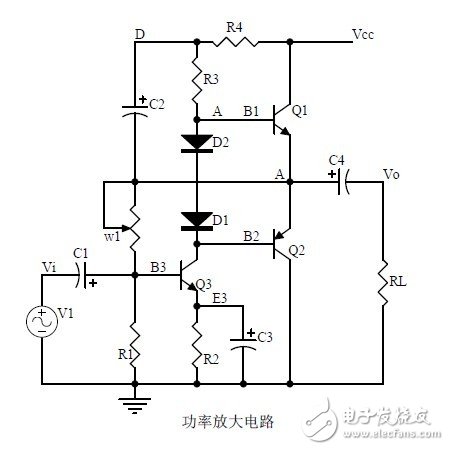
Twenty, power amplifier circuit
Conecting Terminals Without Screws
Conecting Terminals Without Screws,Cold Pressing Terminals,Low Pressure Cold Shrinkage Terminal,Cold Shrinkage Cable Terminals
Taixing Longyi Terminals Co.,Ltd. , https://www.lycopperlugs.com