Engineer STM32 MCU Learning Basic Notes (4): Using PWM to Realize Firefly Lights
Using the PWM method to achieve the firefly light
Last time I mentioned the use of TImer's PWM function to implement the firefly light. Of course, I still need to find a ready-made example to make a change. The example to be used here is here.
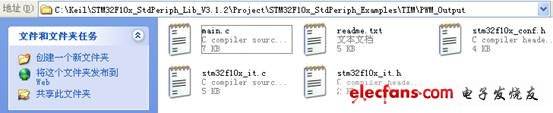
Make a copy into your own practice folder and create a project.
Read the readme.txt and source program first to get some basic information.
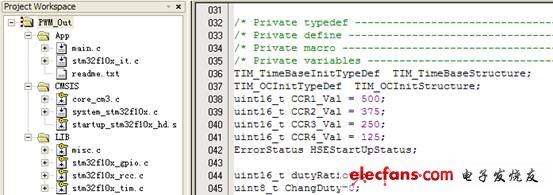
From the program you can know:
(1) Using TIM3
(2) The clock frequency of the timer is 36MHz.
(3) The frequency of the PWM signal is 36KHz, which is set by the ARR of the TIM3. The value of ARR is 999, so the frequency of the PWM is 36MHz / (999 + 1) = 36KHz.
(4) The duty cycles of the four channels are determined by TIM3_CCR1~TIM3_CCR4, respectively:
(TIM3_CCR1/ TIM3_ARR)* 100
Thus, when the frequency of the PWM is 36K, the duty cycle resolution is close to 0.1%. Reduce the frequency to get a higher resolution.
To complete the fade-in and fade-out control of the lamp, it is only necessary to change the value of TIM3_CCR1 periodically.
How to change it? The system timer (SysTick) provided by STM32 is used here.
The description of this timer in the data sheet is as follows:
-------------------------------------------------- -----------
System timebase timer
This timer is dedicated to the real-time operating system and can also be used as a standard down counter. It has the following characteristics:
â— 24-bit down counter
â— Automatic reload function
â— A maskable system interrupt can be generated when the counter is 0
â— Programmable clock source
And its use can be found in the examples provided by the library.
There is an initialization function:
Void SysTick_Configuration(void)
{
If (SysTick_Config((SystemFrequency) / 10))) //The actual test found that dividing by 10 is 100ms, dividing by 100 is 10ms, and so on.
{
/* Capture error */
While (1);
}
NVIC_SetPriority(SysTick_IRQn, 0x0);
}
It is initialized here to generate an interrupt every 100ms.
Put this function in main.c and call it in the main function to complete the initialization. There is an interrupt handler in system32_it.c.
Void SysTick_Handler(void)
{}
In the original example, there is no code written here. You can add relevant code to handle the events every 100ms.
code show as below:
Extern uint16_t dutyRatio;
Extern uint8_t ChangDuty;
Void SysTick_Handler(void)
{ static uint8_t Counter;
If(Counter)16)
dutyRatio-=62;
Else
{ dutyRatio+=62;
If(dutyRatio)999)
dutyRatio=999;
}
If(++Counter)=32)
Counter=0;
ChangDuty=1;
}
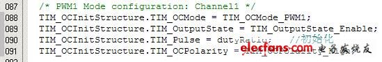
Two variables are defined here, one is dutyRatio, which is used to control the change of duty cycle. It is defined in main.c and initialized to 6. This variable is used when initializing the TIM3_CH1 channel.
Each interruption is increased or decreased depending on the situation, and the amount of each change is 62. In the SysTick_Handler function, a static variable Counter is defined, whose value varies from 0 to 31. When the value is between 0 and 15, the dutyRatio is incremented by 1 each time, so that the total value is 16 times, that is, the final value is: 6+16*62=998, which is exactly one less than the value of ARR. When the value of Counter changes between 16 and 31, dutyRatio is decremented by 62 each time. Thus, the value of dutyRatio always changes between 6 and 998, corresponding to the duty cycle:
6/999*100%=0.6% ~ 998/999*100%=99.89% change.
ChangDuty is a flag that is used to notify the main function that the duty cycle has changed and requires updating CCR1. The Mina function is processed as follows:
While (1)
{ if(ChangDuty==1)
{
TIM3-"CCR1=dutyRatio;
ChangDuty=0;
}
}
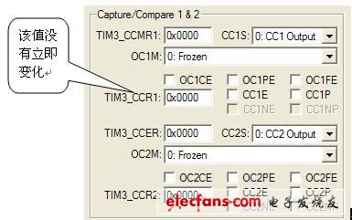
When emulating with software, when executing to TIM3-"CCR1=dutyRatio;, the corresponding values ​​in the peripheral components do not change immediately. It’s not clear whether it’s a debugger or not.
Using hardware to test, because I don't have LEDs on the board TIM3_CH1, I can't see the effect of the light, but it doesn't matter, there is an oscilloscope. After downloading the program into FLASH, run it and observe GPIOA.6, you can see very beautiful waveforms. By measuring the voltage of this pin with a multimeter voltage file, you can see that the voltage rises and falls smoothly. So, I have some doubts that the CCR1 mentioned above does not change immediately, just a debugger problem. //The blue word is wrong, there are instructions below.
Lost Mary OS5000 Vapes combine performance and style with their ergonomic shell and mesh coil for improved flavor profiles. Each Lost Mary Disposable Vape is rechargeable via USB-C charging cable and contains 13ml of vape juice. Lost Mary OS5000 rechargeable vapes, designed by Elf Bar, also provide a battery indicator that allows vapers to check on power levels while they are vaping. Green (high battery), blue (medium battery), and red (low battery) LED colors display the amount of charge left in the 650mAh battery.
Lost Mary vapes are a range of disposables that are easy to use and available in a wide range of flavours. With a focus on fruit and menthol blends, the Lost Mary BM600 vapes deliver a sweet and cool taste with every inhale – the same goes for the Lost Mary AM600 vapes. Speaking of inhaling, that`s all you need to get started, just inhale on your device`s mouthpiece and it will activate instantly. Plus, the 20mg nic salt in each delivers a smooth throat hit.
lost mary vape,lost mary bm3500,lost mary vape review,lost mary os5000,lost mary elf bar.
Hongkong Onice Limited , https://www.ousibangvape.com