Find the perfect connector through simulation, from height matching to reality
With the rapid increase in the number of mobile communication users, the market's demand for high-speed communications is also growing. Related companies and industry groups are fighting day and night to meet this challenge. The speed of 5G networks is expected to be 100 times faster than 4G LTE, and the broadband connection speed can be increased by 10 times. “We need to solve many problems in order to transform 5G technology from concept to practical application.†Bill Rosas, co-founder of Signal Microwave, said, “Our first priority is to be able to implement 5G technology as a whole, and we must also address the need for network testing. To update the system interconnection technologies."
For the connector, even small technical details are worth investing a lot of research and development. The role of these irreplaceable electromechanical components is to connect the electrical terminals and ensure that the terminal can properly transmit electromagnetic energy to another component through a transmission line to achieve data transmission or analysis. All electronic devices and systems are inseparable from the connector, its accuracy is very important for the circuit that transmits the information, especially in the data transmission rate is increasing day by day, the importance of the connector is self-evident.
Eric Gebhard and Bill Rosas co-founded Signal Microwave Corporation, whose core business is to provide custom connectors for signal integrity analysis. Signal Microwave has the ability to continuously improve the data transmission rate of the circuit to meet the needs of optimizing RF, microwave and millimeter wave connectors, laying a solid foundation for the future development of 5G.
The complexity of increasing frequency
Professionals engaged in the design of radio frequency (RF) connectors face a series of problems. On the one hand, they need to consider the geometric shape, size, and transmission limitations. On the other hand, they must ensure that the impedance of the connector and the transmission line match each other. Rosas said: “The component manufacturers of 5G applications are impeccable in terms of delivery speed, and the ability to develop and deliver high-performance components is the key to success in the market competition.â€
As the frequency increases, small distortions caused by geometrical or material selection can be amplified, making it more difficult to ensure impedance matching. The photo in Figure 1 shows the RF connector designed specifically for developing 5G communications applications.
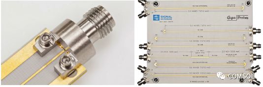
Figure 1. Close-up view of a transmitter converter (left); Test circuit board made by a 5G system engineer (right).
Simulation can help designers in-depth optimization of the key components of the RF infrastructure, and Gebhard and Rosas have shown a strong interest in specific implementations. Signal Microwave has a broad customer base, some of which engineers develop high-frequency devices with frequencies from 40 to 110 GHz for the communications, commercial and military applications.
Design RF Connector
Multiphysics simulation allows Eric and his team to quickly respond to the design challenges presented by each new customer. Gebhard said: "COMSOL software can interact with a variety of design tools, this feature allows our team to efficiently develop and optimize the connector to meet the individual requirements of customers in different industries." This approach shortens the time to market Time, reduced overall development costs, and reduced demand for investment. In addition, because the component designer does not need to consider the security issues of the connected components, this allows them to confidently devote all their energy to other critical aspects.
In simple terms, designers need to convert the mechanical components of an electrical connector into a transmission line. In designing RF connectors, the primary design goal is to create components that can achieve "electrical stealth", that is, by minimizing resistance and energy loss by keeping the connectors substantially similar to the rest of the transmission line. Gebhard said: "The impedance mismatch will cause return loss, resulting in signal distortion or attenuation. We want to minimize this problem." With simulation analysis, designers can optimize the product before manufacturing and testing. .
Finding the perfect connector through simulation
Normally, Signal Microwave's customers will ask for the specific geometry of the single connector and pre-determine the impedance, and they will then perform the rest of the design work. Gebhard and Rosas used a holistic approach to designing the connector and pre-incorporated the overall board and device requirements prior to design. The team typically builds geometry in Solid Edge® software, imports the geometry into COMSOL Multiphysics®, and then uses the RF modeling capabilities in the software to analyze and optimize the design.
Gebhard simulated the measured voltage standing wave ratio, return loss and insertion loss, and the power loss caused by impedance mismatch or unexpected discontinuity. These parameters should be minimized. For example, the voltage standing wave ratio measurement of the test board in the Signal Microwave component is less than 1.5:1, which is in agreement with the simulation results and shows that the reflected power and return loss are sufficiently low (Figure 2 left). Based on the simulation results, the team judged that the insertion loss was relatively flat, and the loss gradually increased with increasing frequency (Figure 2 right). With multiphysics simulation, the Signal Microwave team built a combination of solderless edge connectors with minimal reflected power, which can be extended to the millimeter wave range.
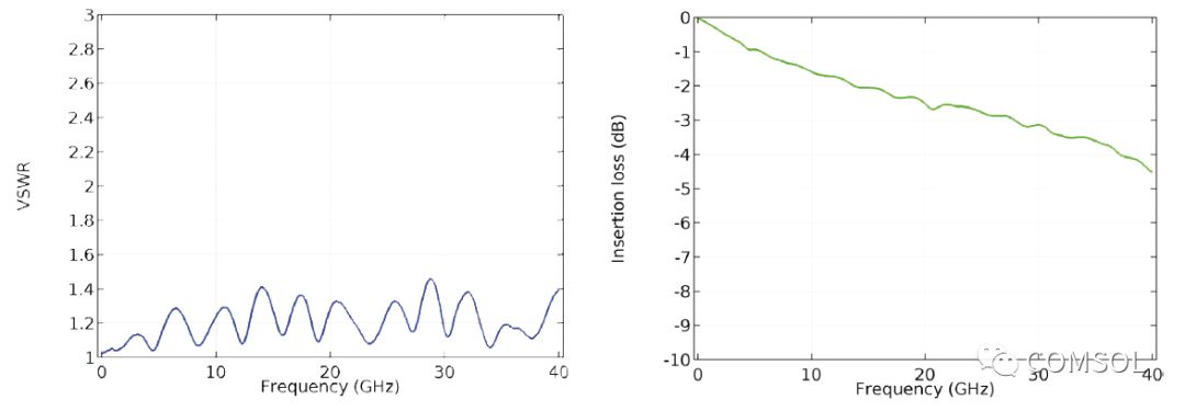
Figure 2. Voltage Standing Wave Ratio (VSWR) measurements (left) and insertion loss (values ​​of the S21 parameter in dB, refer to the figure to the right) of the test board in the Signal Microwave part.
Edge Start Connector
Gebhard also simulated two edge-start connectors, which use a 50-ohm coaxial lumped port for excitation and termination. In this case, a grounded coplanar waveguide circuit board was fabricated on a substrate of 8 mils (capacity units) with a dielectric constant of 3.55. Metal vias connect a pair of ground planes of a coplanar waveguide to the bottom ground plane (Figure 3).
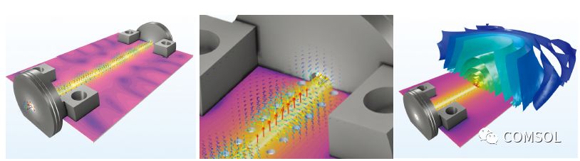
Figure 3. Test board simulation image of a high-speed interconnect application that incorporates 5G and satellite communications technologies. At 20 GHz, the cloud and arrow plots of the modulus in dB in the electric field (left). An enlarged version of the first drawing (center). At 1 GHz, the isosurface of the electric field mode in dB at the top of the circuit board's electric field (right).
Gebhard explained: "In order to successfully implement the 'electrical stealth' of the connector, the approach we take is to minimize reflections by carefully examining geometric discontinuities. In the process we used S-parameters to describe the return loss."
In addition to minimizing return loss by modifying the geometry, Gebhard can also obtain the required impedance by optimizing the dielectric material. In some cases, Gebhard also uses COMSOL® software to calculate structural design-related issues such as the minimum force required to remove the pins on the connector body.
From height matching to becoming a reality
Gebhard has also developed a blind plug connector with a frequency of 70 GHz that can be used for automatic test equipment. After completing the creation of the radio frequency model in software, he produced a physical prototype. Surprisingly, the connector prototype did not work as expected. After careful analysis of the physical prototype, Gebhard realized that there was a slight flaw in the connector. After engineering and technical appraisal, Gebhard returned to the original model and added flaws. In the end, the simulation results match the physical test data perfectly.
“The virtual design is correct, but the physical prototype has a flaw that we did not anticipate. After detailed testing of the prototype, we found the problem and added the defect to the virtual model. Finally, the generated simulation results. It is exactly the same as the observed problem. For us, this is really an experience of a flash of light."
“In this case, I was pleasantly surprised to see that the simulation results are so highly consistent with reality. We have subsequently added some special ideas to this RF connector design and are very much looking forward to seeing the performance of these connectors with their own eyes.â€
High-precision simulation tools allow Gebhard to design and manufacture custom connectors for professional RF applications without constraints, which not only reduces the need for physical prototypes, but also effectively shortens the development cycle.
Diy Game Kit,Arcade Joystick Diy,Diy Game Console Kit,Diy Handheld Game Console Kit
Guangzhou Ruihong Electronic Technology CO.,Ltd , https://www.callegame.com