Overview of the structure and function of the low-voltage reactive power compensation device MSCGD
Low-voltage capacitance compensation cabinet is also called low-voltage reactive power compensation device MSCGD. The working principle is that the load current provided by the power grid to the power equipment consists of active current and reactive current. The reactive current is exchanged between the power supply and the load and reciprocally. Occupying the power grid greatly reduces the power supply capacity of the power supply equipment and reduces the power factor. It is to use the capacitive reactive current generated by the device to track and offset the inductive reactive current in the power grid quickly and accurately, so as to improve the power factor, ensure the quality of the power supply, increase the power supply capacity of the power supply equipment, and reduce the loss in the circuit.
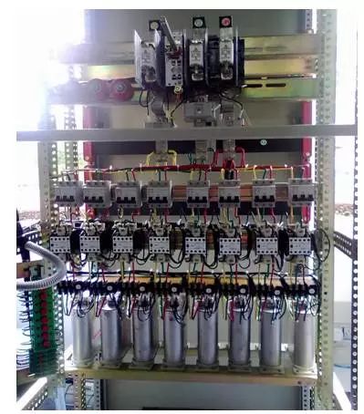
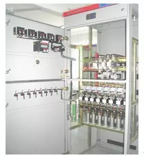
In general, low-voltage capacitance compensation cabinet consists of cabinet shell, busbars, circuit breakers, disconnectors, thermal relays, contactors, arresters, capacitors, reactors, primary and secondary conductors, terminal blocks, power factor automatic compensation control devices, and disk surfaces. Instruments and other components.
Capacitor cabinet function and its structure

The role of capacitor compensation cabinet
The function of the capacitance compensation cabinet is to increase the power factor of the load, reduce the reactive power, and improve the efficiency of the power supply equipment; whether the capacitor cabinet can work normally can be judged by the reading of the power factor meter, and if the power factor meter reading is around 0.9, it can be regarded as normal.
Capacitor cabinet circuit principle
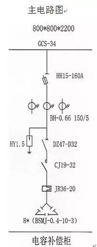
The working principle of a circuit
Close the knife melting switch and circuit breaker. The reactive power compensation controller outputs the control signal according to the phase difference between the voltage and current of the incoming cabinet and controls the AC contactor to close and open, thus controlling the capacitor input and output.
Analysis of the role of components
HH15-160A knife fuse switch
HH15 (QSA) series switch fuse sets combine load switch and fuse short-circuit protection functions into one, compact structure, safe use, mainly used in power distribution and motor circuit with high short-circuit current as power switch and emergency switch, and The short circuit protection of the cable is particularly suitable for installation in drawer type switch cabinets due to the rotary operation of the switch handle.
The switch series fully enclosed structure consists of contact system, operating mechanism and handle.
The contact system consisting of the moving and static contacts and the arc extinguishing device is assembled in a closed casing made of a new arc resistant engineering plastic to achieve zero arcing; its working performance is stable and reliable, and no user is needed during the service life. Maintain or replace parts.
The high breaking capacity knife-type contact fuses used are connected in series between the contacts. When the switch is in the open position, the exposed conductive parts are not energized to ensure the safety of repairing and replacing the fuse-links (open the door switch Is in a disconnected state).
The switch has an operating mechanism of spring energy storage. The operating mode of the handle is rotation operation. The switching and closing operations of the switch are completed by spring force, and all of them are independent of manpower to ensure the reliability and stability of the operation.
HY1.5 low voltage arrester
HY1.5W-0.28/1.3, HY1.5W-0.5/2.6 low voltage zinc oxide surge arrester, the product is used to protect the insulation of the AC power system electrical equipment from atmospheric over-voltage and operating over-voltage, and is suitable for the distribution box. Power frequency 50Hz or 60Hz. When installing, firstly fix the lightning arrester on the bracket or the crossarm, ground the lower grounding terminal directly, and then fix the upper lead on the connection terminal. HY zinc oxide surge arresters are also called silicone rubber zinc oxide arresters, also called organic metal oxide arresters.
DZ47-63/D32 Molded Case Circuit Breaker
DZ47 series miniature circuit breakers are mainly used in AC 50/60Hz, rated operating voltage 240V/415V and below, rated current up to 60A circuit, the circuit breaker is mainly used for the control of modern electrical circuit and equipment, overload, Short circuit protection also applies to infrequent operation and isolation of the line.
DZ47 series miniature circuit breaker is composed of plastic shell, operating mechanism, contact arc extinguishing system and tripping mechanism. The tripping mechanism is composed of bimetal overload and inverse time-delay tripping mechanism and short-circuit instantaneous electromagnetic mechanism. The contact arc extinguishing system adopts a special arc-guiding angle and aisle quenching chamber, and has a significant current-limiting characteristic.
BSMJ-0.4-10-3 capacitor
"BSMJ" self-healing low-voltage shunt capacitor adopts advanced metallized film as material, introduces foreign advanced technology and equipment, and is produced in strict accordance with national standards and IEC standards; it is mainly used for low-voltage power network to increase power factor and reduce line loss. Improving voltage quality is a new type of energy-saving product recommended by the country.
Small size and light weight: Due to the use of metallized polypropylene film material as the medium, the volume and weight are only 1/4 and 1/5 of the old products.
Low loss: The actual value is lower than 0.1%, so the capacitor itself has low energy consumption, less heat generation, low temperature rise, long working life, and good energy saving effect.
Excellent self-healing properties: Partial dielectric breakdown caused by overvoltage can quickly self-heal, return to normal operation, and greatly improve reliability.
Safety: Built-in self-discharge resistors and safety devices. The built-in discharge resistor can automatically discharge the electrical energy on the capacitor. When the capacitor fails, the fuse can be disconnected in time to avoid further development of the fault and ensure the safety of use.
No oil leakage: This capacitor adopts advanced semi-solid impregnating agent, the drop melting point is higher than 70°C, no oil leakage during use, avoiding environmental pollution, and the capacitor will not fail due to oil loss.
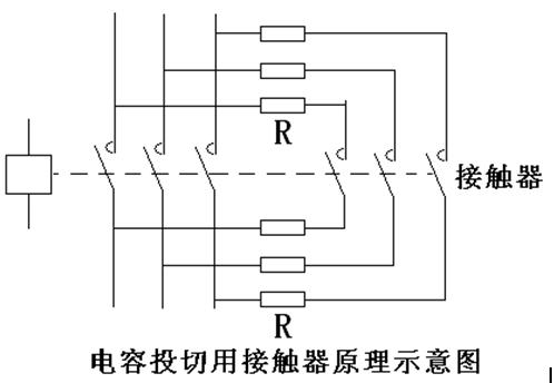
CJ19-32 AC Contactor Contact
Application CJ19-32/11.20.02 series switching capacitor contactor is mainly used in AC 50Hz or 60Hz, rated working voltage to 380V power line for low voltage reactive power compensation equipment to put into or remove low voltage shunt capacitors. The contactor has a device to suppress the inrush current, which can effectively reduce the impact of the closing inrush current on the capacitor and suppress the overvoltage at the time of breaking.
Environmental conditions for use: The altitude of the installation site does not exceed 2000m.
Installation conditions: The inclination of the mounting surface and the vertical surface is not more than ±5°.
Ambient air temperature: -5°C to +40°C. The average value for 24 hours does not exceed +35°C.
Atmospheric relative humidity: no more than 50% at ambient air temperature of +40°C, allowing higher relative humidity at lower temperatures.
The contactor is a direct-acting double-breakpoint structure. The contact system is divided into upper and lower two layers. The upper layer has three pairs of current-limiting contacts and a current-limiting resistor to form a device for suppressing the inrush current. When it is closed, it is turned on for a few milliseconds before the working contact is turned on. The permanent magnetic block in the current limiting contact is released under the action of the spring, and the current limiting resistor is disconnected to allow the capacitor to operate normally. The contactors of CJ19-25~43 have two pairs of auxiliary contacts. The contactors of CJ19-63~95 have three pairs of auxiliary contacts. The contactor terminal is covered by an insulating cover, which is safe and reliable. The coil terminals are marked with voltage data to prevent misconnections.
CJ19-25~43 contactors can be installed with screws, or they can be mounted on 35mm standard rails by the bottom slider fasteners. There is a removable rectangular white card on the mask, users can use it to print the project code and so on.
JR36-20 Thermal Relay
JR36 series bimetal thermal overload relay (hereinafter referred to as thermal relay) is suitable for AC 50Hz, main circuit rated operating voltage to 380V, rated operating current 0.25 ~ 160A circuit, the AC motor overload and phase protection.
The thermal relay has the functions of setting current adjustment, temperature compensation, phase failure protection, automatic reset and manual reset, flexibility check of line action, manual disconnection of normally closed contacts (normally open contacts are not closed) and other functions. Its external dimensions and mounting dimensions are exactly the same as those of the JR16B series. It is a new generation of ideal products.
Current Transformer BH-0.66 150/5
BH-0.66 current transformer is a plastic enclosure, totally enclosed, indoor type product. It is suitable for electrical energy measurement, current measurement and relay protection in power systems with rated frequency of 50HZ or 60HZ and rated voltage of 0.66KV and below.
The BH-0.66 current transformer is a bus type plastic shell type insulation. The lower part of the product has a mounting plate for fixed installation, and the middle window hole is used for the passage of a bus bar.
The installation diagram of a circuit
A circuit connection bus installation and installation of physical map
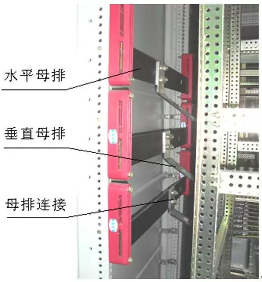
The role of the busbar is to sink and distribute the current. The horizontal busbar size is generally selected according to the rated current of the incoming cabinet, but it must meet the requirements of dynamic stability and thermal stability; the rated current of the vertical busbar is generally 1000A.
Commonly used bus structure types are rectangular, slot and tube.
1 The monolithic rectangular conductor has the advantages of small skin effect coefficient, good heat dissipation conditions, simple installation, and easy connection. The general working current is less than or equal to 2000A.
2 The skin effect coefficient of multiple rectangular conductors is larger than that of a single conductor, so the additional loss increases. Therefore, the ampacity does not increase as the number of conductors increases, especially when more than three pieces per phase, the skin effect coefficient of the conductor increases significantly. In the engineering manual, several pieces of rectangular conductors are suitable for circuits with operating current ≤ 4000A. Above 4000A, slotted or tubular shaped conductors that facilitate the distribution of the alternating current should be used.
3 The groove-shaped or tubular shaped conductors have a small skin effect coefficient, a relatively uniform current distribution, good heat dissipation conditions, and high mechanical strength, but the cost is high and the installation is inconvenient.
Busbar sectional area selection principle
The cross-sectional area of ​​the A branch bus can, in principle, be selected according to the size of the circuit breaker rated current.
B In the case where there is only one line incoming, the section of the main bus (horizontal bus) may be equal to or slightly larger than the cross section of the branch busbar of the line cabinet.
C If there are two incoming loops, the situation is slightly more complicated. At this time, the two-input line cabinets are usually arranged at the left and right ends of the main bus, so that the distribution of the current flow is more reasonable, and the section of the main bus can be selected not according to the sum of the two-input currents. At this time, the section of the main bus should be considered within the range of the current from the larger incoming current to the sum of the two currents. The size of the busbar depends on the arrangement of the incoming and outgoing cabinets, and is determined after the distribution of the current flow is analyzed.
The following conditions must be considered in the selection of the busbar size in the switch cabinet
A long-term heating according to the conductor allows the ampacity to select the cross section;
B thermal stability check;
Verification of C dynamic stability; verification of D conductor resonance
Long-term allowable current value of copper and aluminum bus bars
1) "*" is a special material for low voltage components and is generally not recommended.
2) The table shows the long-term allowable current value when the air temperature is 35°C.
3) When the busbar is laid flat, the current is reduced by 5% for width ≤ 60mm and 8% for width > 60mm.
4) The long-term allowable current value of the low-voltage drawer switchgear shall be set at 0.8 times the current in Table 1.
Neutral conductor (N) selection
If the cross-sectional area of ​​a phase conductor is >10mm2, it is equal to half of the cross-sectional area of ​​the phase conductor and the minimum cross-sectional area is 10 mm2. The cross-sectional area of ​​a phase conductor is ≤ 10 mm2, and the cross-sectional area of ​​the neutral conductor is equal to the phase conductor.
The cross-sectional area of ​​the protective conductor (PE) should not be less than the value given in the table below
| Phase conductor cross-sectional area | The minimum cross-sectional area of ​​the corresponding protective conductor Sp |
| S ≤ 6 | S |
| 16<S≤35 | 16 |
| 35<S≤400 | S/2 |
| 400<S≤800 | 200 |
| S>800 | S/4 |
The cabinet of the switchgear shall be provided with a grounding busbar, which is generally selected from the 4×40TMY copper busbars and the 6×60TMY copper busbars.
Busbar production process
(1) Production process of copper and aluminum busbars (referred to as flat busbars)
Material selection → simulation → blanking → scratching → punching (drilling) → antimony tin (tin plating) → bending → punching (drilling) → flattening (flower) → installation → painting → inspection
Note: The use of tin-plated busbars has eliminated the tin-silicon process.
(2) Copper core insulation round busbar (referred to as cable bus) production process
Selection → Simulation → Blanking → Stripping → Cold (cold pressure) joints → Installation → Finishing → Inspection
(3) Process Flow of Heat-shrinkable Bushing Insulation Bus (Insulated Bus)
Forming bus bar → (insulated pipe → heating → solidification molding) → installation → check
Copper, aluminum bar production process requirements
(1) In addition to the necessary elbow and inclination, the busbar must not be bent or twisted. The busbar width must be no more than 2mm per meter, and the narrow side no more than 3mm per meter.
(2) There must be no obvious hammer marks, scars, or scratches on the surface of the bus bar.
(3) Busbars are to be connected with electrical components. The busbars should be in accordance with the requirements of the hole diameter and the number of holes of the electrical component terminals.
(4) The busbar and the root of the electrical component terminal shall have an empty position of not less than 5mm.
(5) Busbar lap length should be greater than or equal to the bus width or terminal width, and should ensure that the contact surface of the busbar and the terminal is not less than 1.5 times the cross-sectional area of ​​the busbar.
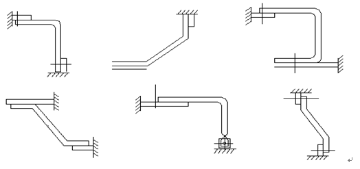
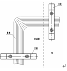
(6) The busbars that are connected to the electrical components shall be bent at an acute angle. The bend angle shall not be less than 90 degrees. See the figure below.
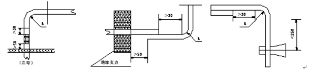
(7) At the start of the busbar bending, the lap joint to the busbar should not be less than 30mm, and the busbar support edge to the nearest insulator should not be less than 50mm, but should not be greater than 250mm, see the following figure.
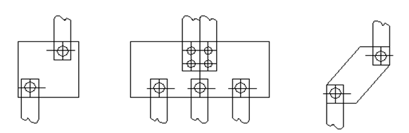
(8) When the width of the bus bar is large and the length is short, the width of the bus bar cannot be bent. When the width of the bus bar of the entry and exit lines is relatively large, it is allowed to have an excessive bus bar, to the side of the bus bar or to change the bus bar without affecting the lapping area. connection. See below
(10) The busbar should not be bent at right angles, and the bending radius must not be less than the R value specified in the following table. After the busbars are bent, there must be no cracks and serious wrinkling. The wrinkle height must not exceed 1mm.
(11) Busbar lap joints shall be treated with antimony tin. The length of antimony tin shall be greater than the lap length of 20mm. For most of the lap joints that cannot be tin-removed, it is allowed to be treated with conductive paste.
(12) The lacquer color and phase sequence of busbars shall be as specified in the table below (front face of the cabinet)
(13) The lap joint surface of the busbars shall not be painted, the paint color shall be uniform, the interface of the paint shall be straight, there shall be no obvious bending or straightening, and the paint boundary of the busbar ends of the same side of each phase shall not be obviously irregular Phenomenon, the limit from the contact surface shall not exceed 20mm.
Copper core busbar production requirements
(1) When the cable is connected to an electrical component, a copper connector must be used.
(2) The copper connector must not be crimped with the aluminum core wire.
(3) The length of the insulation stripping insulation layer should be 3mm longer than the copper bushing sleeve.
(4) When the insulated wire is stripped of the insulating layer, it is not allowed to break the core and damage the core.
(5) After inserting the wire into the copper connector bushing, punch it with a mold on a punch press or crimp it with a cold press nipper. Then pull the wire firmly. The wire should not be pulled out of the copper connector or loose.
Secondary circuit diagram analysis and installation
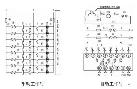
Secondary schematic
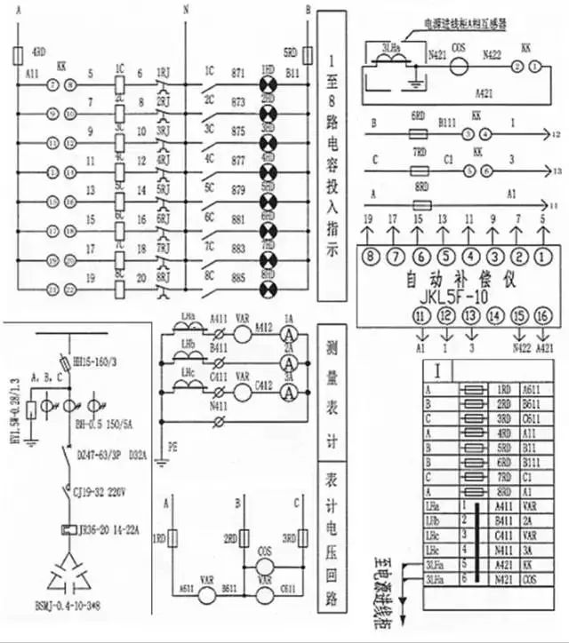
Secondary circuit working principle
When working manually, the changeover switch KK starts from kk21-22 and turns on one more LED lamp per one position, indicating that 1-8 capacitors enter the use state one by one; when it is turned on automatically, the changeover switch KK stops at the kk1-2 position. Next, stop at the rest of the site. (As shown below)
Secondary circuit components layout
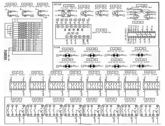
Secondary circuit installation wiring diagram
Secondary circuit installation process
Use tools such as wire strippers, scissors, wire batch, crimping pliers, socket wrenches, pointed pliers, curved pliers, take-off lights, adjustable wrenches, and electrical tools.
According to the drawings, install secondary system relays, meters, signal lamps, terminal blocks and other electrical components and accessories.
According to the layout of the pasting element number, the label is generally affixed to the middle of the upper part of the metal frame, individual elements can not be pasted on the label, you can choose the appropriate location near the paste.
Determine the wiring route according to the drawing. According to the wiring route, correct blanking (usually lengthened 300 ~ 500mm), and both ends of the mark or put on the line number, that is, according to the wiring route to lay.
The laying of conductors shall be horizontal and vertical, and the level shall be beautiful and clear. It shall be tied with a tie or wound with a ribbon. The secondary wire can be laid in a plastic line trunking used for wiring. In this case, only the conductors need to be clearly organized and not required to be bundled.
installation steps
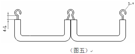
The installation wiring shall be connected according to the wiring principles of left rear right, top to bottom, inside out, and then easy. First connect the reactive power meter, ammeter, and voltmeter; then connect the automatic compensator and universal switch; after the completion, the bundling line should keep the horizontal and vertical angle 90°. A certain length of wire should be left for the terminal block wiring. The maximum number of wires for the terminal screws on each terminal is 2 wires. For the connection between the terminals, use the method shown in Figure 5. Then connect the current transformer, AC contactor, and thermal relay.
5, insulation resistance test, dielectric strength test
5.1. Testing Insulation Resistance with 500 Volt Insulated Shaker Test Method
(1). Remove all connections to be tested and discharge before being tested.
(2). The measured object should be in good insulation during the shake test.
(3). Reliably touch the test leads on the capacitor electrodes.
(4). Measure the resistance of the three terminals of the capacitor to the housing.
(5). After the oscillating generator charges the capacitor for a certain period of time and reads the data, the test wire shall be quickly disconnected from the test object to cut off the circuit, so as to avoid the residual charge of the charged capacitor passing through the oscillating meter circuit. The discharge leaks and breaks the indication pin, and burns the internal components such as the shaker's internal diode.
5.2 power frequency and impact pressure
During the test, the circuit breaker (load switch or contactor) and disconnector must be closed, the high voltage fuses must be shorted, and all removable parts must be in working position. However, when circuit breakers (load switches or contactors), disconnectors are in the open state or the removable parts are in a removed, tested or grounded position that can cause more unfavourable electric field conditions, then must be done under that condition Once, that is, closing, opening, pulling, should be tested according to the above conditions.
In the impulse withstand voltage test, the test object shall not be provided with an overvoltage protection element. The secondary side of the current transformer shall be short-circuited and grounded. The current transformer with a low current ratio shall allow the primary side to be short-circuited.
The auxiliary loop and control loop shall be able to withstand the 2500V power frequency withstand voltage test and perform the following requirements:
Connect the auxiliary loops together and apply the test voltage between it and the grounding frame.
Each part of the circuit that is insulated from other parts in normal use is used as a pole, other parts
If there is no breakdown in each test, it is considered to pass.
Protection circuit effectiveness
| Test Department | When the main switch is disconnected between the electrodes in and out | When the main switch is closed between different live parts, between the main circuit and the control circuit and the metal frame | Control circuit between metal frames | Insulated handle to main circuit | ||||
| A | B | C | A-BCPE | B-ACPE | C-ABPE | PE | H-ABC | |
| Insulation resistance mΩ | 500 | 30 40 35 | 50 | 40 | ||||
| AC voltage v | 380 | 380 | 380 | 380 | ||||
Insulation resistance and AC withstand voltage
| The measured resistance value | Resistance/mΩ | The measured resistance value | Resistance/mΩ |
| Instrument door to ground | 30 | Open bracket to ground | 35 |
| Operation handle to ground | 50 | Terminal board to ground | 30 |
| Knife switch bracket to ground | 25 |
LANA Vape Stick 1500 Puffs is so convenient, portable, and small volume, you just need to take them out of your pocket and take a puff,
feel the cloud of smoke, and the fragrance of fruit surrounding you. It's so great.
We are China leading manufacturer and supplier of Disposable Vapes puff bars, lana vape stick 1500 puffs kit,lana vape stick 1500 puffs plus,
lana vape stick 1500 puffs rechargeable, and e-cigarette kit, and we specialize in disposable vapes, e-cigarette vape pens, e-cigarette kits, etc.
lana vape stick 1500 puffs kit,lana vape stick 1500 puffs plus,lana vape stick 1500 puffs rechargeable,lana vape stick 1500 puffs vape pen,lana vape stick 1500 puffs box
Ningbo Autrends International Trade Co.,Ltd. , https://www.mosvapor.com