Challenges in designing battery-powered industrial equipment
Portable electronic point-of-sale (EPOS) devices are gaining popularity worldwide. Unlike traditional desktop devices, portable EPOS devices have limited battery life and require frequent charging via the USD interface or other connection devices.
As fast charging technology is growing in the portable electronics market, it is likely that portable EPOS devices will also use this feature. As the portable device starts to use a larger battery, the quick charge requires a charging adapter that can provide more power. Different manufacturers have proposed some methods, but each method requires a higher input voltage to the power connector. Higher input voltages allow more power to enter the system for fast charging without exceeding the ampacity limit of the connector. The adapter voltage is set to the normal 5V (USB VBUS) level by default, but the signal transmission on the D+/D- data line between the external adapter and the mobile device allows the adapter to output a higher voltage as required. Depending on the adapter capacity, typical values ​​include 5, 9, 12 or 20V output stages. The charging integrated circuit (IC) or application processor in the system controls this signal transfer so that the adapter outputs a suitable voltage level.
Usually, when plugging into a USB connector, you need to use an analog switch to transfer power between the microcontroller [MCU] and the battery charger, as shown in Figure 1 with the bq25890 fast charger with MaxChargeTM technology. When connected for the first time, the MCU controls D+/D-. It will detect whether the adapter is a USB connector or a USB connector.
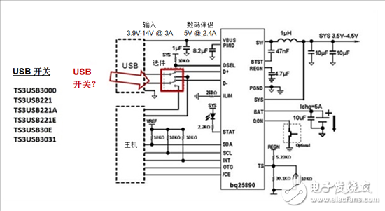
Figure 1: Typical Application Diagram Using USB and Charger Applications
Depending on the connected device, signals through the USB connector may be sent to different destinations. This requires the USB switch to send the signal correctly. In this case, any USB switch that matches the design bandwidth, configuration, and voltage range can be used. TI offers a variety of USB switches with a wide range of options in terms of configuration, voltage range, on-resistance (RON), and bandwidth.
The application processor cannot tolerate high voltages. Since fast charging is usually operated at 9V and the MCU cannot tolerate 9V, it must always be avoided that the MCU is exposed to this voltage.
The USB connector socket has four pins, VBUS, D-, D+, and GND from right to left as shown in FIG. After the protocol is quickly charged, the VBUS voltage will be 9V.
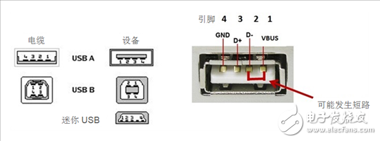
Figure 2: USB Switch and Pin Description
When the VBUS voltage reaches 9V, if the USB plug is not inserted or pulled out at a certain angle, the VBUS pin of the connector may be short-circuited with the D-pin. This will cause the MCU connected to the D-pin to be exposed to VBUS, thus damaging the MCU, as shown in Figure 3.
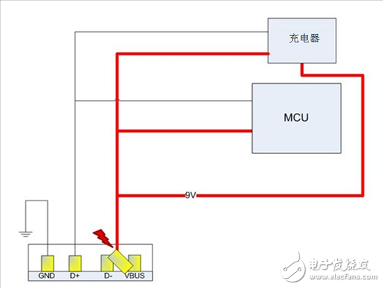
Figure 3: The consequences of a short circuit without the TS3USB3000 at 9V.
TS3USB3000 USB switch can protect MCU under 9V voltage condition, and switch between MCU and charger/Universal Asynchronous Receiver/Transmitter (UART) at the same time, as shown in Figure 4. After the charger is connected to the USB port, the MCU will detect the connected charger and pull the output enable (OE) pin high to disable the switch. The MCU will communicate with the charger, indicating that it can adopt a faster charging mode with the VBUS protocol at a voltage of 9V, as also shown in FIG. The TS3USB3000 is now in a low power state, the switch is disabled and the MCU can be protected.
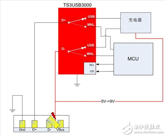
Figure 4: The TS3USB3000 protects the MCU under 9V conditions in the event of a short circuit
The TS3USB3000 switch has two uses: switching between the host and the charger and protecting the MCU from 5V to 9V. For the first use, you can use any USB switch, depending on the bandwidth and RON type required by the design. However, for the second purpose, special USB switches such as the TS3USB3000 are required to provide short-circuit protection for the MCU.
The TS3USB3000 can achieve these two uses for designs that require operation at 9V. The device can easily switch between the host and the MCU, and it can protect the MCU if a short circuit occurs between the VBUS and the D-pin when plugging or unplugging the USB connector.
Dynamic switching device is a non-contact, high reliability and fast switching switch used in dynamic power factor compensation equipment. It is especially suitable for fast and wear-free switching occasions. Typical applications include lifting equipment, elevators, electric welding machines and other occasions with frequent reactive power changes
Dynamic Switching Device,Capacitor Dynamic Switch Device,Capacitor Reactor Controller,Capacitor And Reactor Dynamic Switching Device
Jiangsu Sfere Electric Co., Ltd , https://www.elecnova-global.com