Modbus communication and serial communication check bit description
Serial communication
Commonly used RS232 and RS485
RS232:
Full duplex, cable length up to 15.2m TXD; receive RXD
Logic 1 (MARK) = -3V to -15V Logic 0 (SPACE) = +3 to +15V
RS485:
Half duplex, cable up to 1200m cable system: two lines, A, B
Multiple device connections: all A parallel, all B parallel
RS485 to USB. After the driver is installed, there will be one more serial port (COM port). You can modify the serial port number COMN in Properties=â€Advancedâ€.
Serial (and modbus) configuration
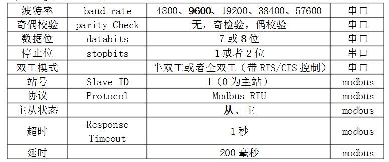
1Bit when the stop bit is checked, 2Bit when there is no check bit
TTL (transistor-transistor logic level) level signal. +5V is equivalent to logic "1" and 0V is equivalent to logic "0"
modbus-RTU protocol:
RS485 is hardware and modbus-RTU is protocol. The RS485 is running on modbus-RTU, so it is confused.
The MODBUS protocol uses a master-slave response type connection (half-duplex) master query on a communication line, and the slave responds
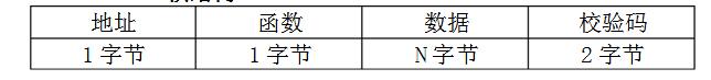
modbus-RTU frame structure
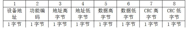
General host query
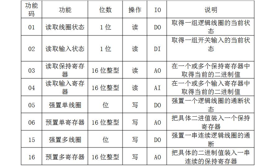
Common function code
Different data devices, different data bits start address: 0001
Preemptive status by default, post highs
Error check (CRC) is calculated using serial debugging software
Some communication CRC high byte first, some communication CRC high byte behind
Modbus communication and serial communication check digits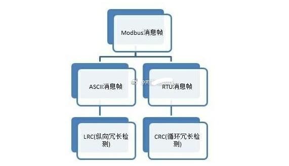
Data exchange between devices can be achieved using the Modbus protocol. Modbus communication theoretically supports four types of ModiconPLC addresses, namely 0*, 1*, 3*, and 4*, which represent data addresses such as open (intermediate coil), open, analog, and analog (intermediate register). It does not correspond to the open, open, mold in, or die out addresses in Siemens or other devices. Can be understood as 0* and 1* corresponding bit address read and write operations, 3* and 4* word address read and write operations.
Here, 0*, 1*, 3*, and 4* indicate that there are 5 digits in length and 6 digits in some cases. Actually, this is irrelevant to Modbus communication, but it is related to the representation of software.
The most commonly used Modbus communication is the RTU read request format:
Slave address (1 byte), function code (1 byte), slave data start address (2 bytes), read data length (2 bytes), CRC check (2 bytes )
It can be seen that only the start address and the communication length of the start slave data area can be set.
In particular, the Modbus address complies with the IEC1 address standard (minimum address *1) and Siemens follows the IEC0 standard (minimum address 0, eg M0.0). Therefore, address translation is required when communicating with different standard addresses. That is, one operation is added.
A simple error detection method in serial communication. There are four ways to detect errors: even, odd, high and low. Of course, no check digit is also possible. For even and odd parity cases, the serial port will set the parity bit (the bit following the data bit) and use a value to ensure that the transmitted data has even or odd logic highs. For example, if the data is 011, the parity bit is 0 for even parity, ensuring that the logic high number of bits is an even number. If it is odd parity, check bit 1, so there are 3 logical highs. The high and low bits do not really check the data, simply set logic high or logic low. This allows the receiving device to know the status of a bit and has the opportunity to determine whether there is noise that interferes with the communication or whether the transmitted and received data are not synchronized.
Shenzhen Xcool Vapor Technology Co.,Ltd , https://www.szxcoolvape.com