Thermometer
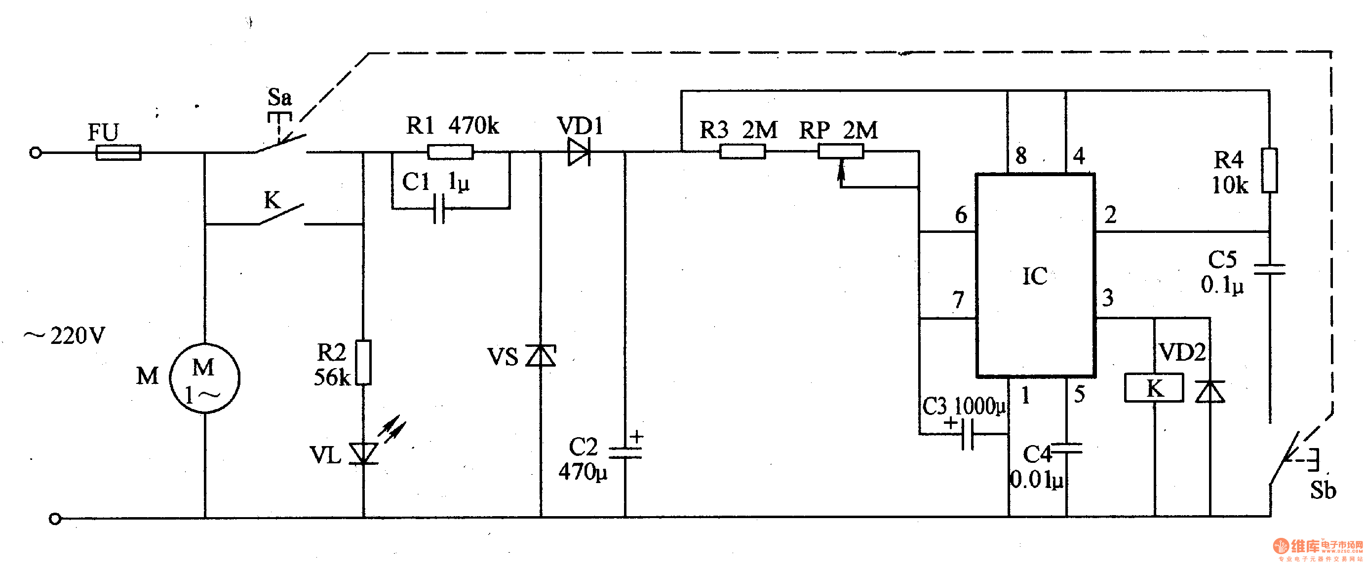
The power circuit is composed of a fuse FU, a power button S (Sa, Sb), resistors R1, R2, capacitors Cl, C2, a power indicating LED VL, a Zener diode VS, and a rectifier diode VD1.
The meter timing control circuit is composed of resistors R3, R4, potentiometer RP, capacitor C3-C5, relay K and diode VD2.
Connect the power supply, press the power button S, the AC 220V voltage will be VL after the R2 current limit voltage drop; the other channel is stepped by Cl, VS voltage regulation, VDl rectification, C2 filtering, then the meter The timing control circuit provides a +12V operating voltage. After the IC is energized, since the voltage of the 2 pin is lower than 4V, the high output of the 3 pin makes the K energize and pull, the normally open contact of K is turned on, so that the power is self-locked after the reset, and the motor M is driven by the meter. Power on work.
At the same time, C3 is quickly discharged through the 7-pin circuit of the IC, and then discharged through RP and R3. When the voltage across C3 is charged above 8V, the circuit in the IC is turned over, and the 3 pin changes from high level to low level. Flat, K is released, its normally open contact is disconnected, the working power of the whole machine is cut off, M stops, VL goes out, and a watch action is completed. If you need to start the meter again, just press S again.
Adjusting the resistance of the RP can change the timing of the C3 charging (ie, the timing time), thereby controlling the running time of the M.
Component selection
Rl-R4 uses 1/4W metal film resistor or carbon film resistor.
The RP uses a small organic solid potentiometer.
Cl selects CBB capacitors with a withstand voltage of 400V or higher; C2 and C3 select aluminum electrolytic capacitors with a withstand voltage of 16V; C4 and C5 use monolithic capacitors or polyester capacitors.
Both VDl and VD2 use 1N4007 silicon rectifier diodes.
VS selects 1W, l2V silicon Zener diode, such as 1N4742 and other models.
VL selects high brightness LED of φ3mm.
The IC selects the NE555 type time base integrated circuit.
K selects JRX-l3F type l2V flow relay.
S uses a small bipolar moving button.
M uses a miniature 220V AC motor.
There are many different versions of DIN Connectors. The name of each type comes from the number of pins the connector has (3-pin DIN, 4-pin DIN, etc.) Some of these pin numbers come in different configurations, with the pins arranged differently from one configuration to the next.
DIN cable connector 3-pin, 4-pin, 5-pin, 6-pin, 7-pin, 8-pin degree 180, 216, 240, 262, 270
DIN cables, DIN connector, telephone cable, computer cable, audio cable
ETOP WIREHARNESS LIMITED , https://www.oemwireharness.com