Stepper motor drive circuit schematic
Single chip microcomputer STM32L151CCU6
KT2520K26000DCW28QAS import spot
MOSFET imported original FET
IR brand IRFP3306PBF special treatment original imported absolutely original
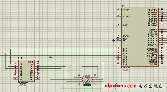
Figure stepper motor drive circuit schematic
Wall Boiler Pressure Gauge,Digital Tire Gauge,Boiler Manometer,Capillary Tube Pressure Gauge
ZHOUSHAN JIAERLING METER CO.,LTD , https://www.zsjrlmeter.com