Detailed remote control circuit design analysis - circuit diagram reading every day (270)
The remote control is a device used to remotely control the machine. Modern remote controls consist primarily of integrated circuit boards and buttons used to generate different messages. Electronic enthusiasts can make remote control circuits, which can be made by using special integrated circuit boards. However, mastering the principles of some common remote control circuits is very helpful for improving their own technology. The single-channel, single-user remote control circuit is the simplest one in the remote control circuit, and the circuit is usually used for optical and acoustic control.
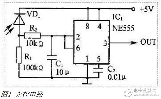
First, the light control circuit
Figure 1 shows a light control circuit constructed using a 555 time base circuit. Because it does not require a dedicated transmitter, it is a telemetry circuit. The photodiode VD1 is used for light detection and conversion, and different performance photodiodes can be used as needed to convert infrared light or visible light into electrical signals. IC1 uses NE555 to form a Schmitt trigger, which shapes and powers the received optical signal to drive the subsequent circuit. The driving current is up to 200mA, which can directly drive the relay or micro motor. This circuit is a positive logic control, that is, ICl outputs a high level when there is illumination, and outputs a low level when there is no illumination. For negative logic control, simply position VDl and R1. The C1 and R2 integration circuits filter out interference pulses to prevent malfunction. The power supply voltage ranges from 5V to 12V. R1 is adjusted as needed during debugging to make the circuit have appropriate sensitivity. The circuit can be used for infrared detection, anti-theft alarm or danger prohibition alarm; if the optical detection head of the circuit detects the production process, the output is connected to the electronic counter, and can also be used for generating the quantity detection of the online product and detecting the quantity of the paper passing by the printing machine.
Second, the voice control circuit
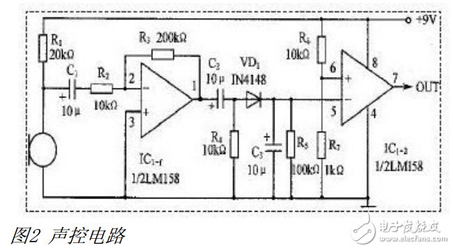
Figure 2 is a sound control circuit composed of a dual op amp LM158, which is essentially a telemetry circuit. IC1-1, which constitutes a 20-fold voltage amplifier, amplifies the voice signal picked up by the micro-electret microphone to a certain amplitude, and is filtered by VD1, C3, and R5, and then sent to the voltage comparator formed by IC1-2. The voltage comparator's reference voltage is taken from the voltage dividing point of R6 and R7, about 0.8V. When there is no voice signal, IC15 pin voltage is 0V, less than the 6-pin reference voltage, output OUT=0; when there is voice signal, 5 feet The voltage is greater than the 6-pin reference voltage, OUT=9V. When debugging, adjusting R3 can change the voltage gain of IC1-1, so that the receiving sensitivity is suitable: R7 can also be adjusted to change the comparator level (reference voltage) to balance sensitivity. And anti-interference requirements (R7 increased, anti-interference ability, but low sensitivity). The power supply voltage range is 5~15V, and other types of op amps are also available for IC1. In general, an op amp can drive a load of more than ten milliamps. The voice signal can be a clapping, a whistle, a percussion, and the like. This circuit can be used for voice-activated switches.
Third, ultrasonic remote control transmitting / receiving circuit
As shown in Fig. 3, the ultrasonic wave is composed of a multi-vibrator composed of 555 timers, wherein RP, R1, and C1 are timing elements, and the formula is calculated by the oscillation period (set W1 = 15.3 kΩ).
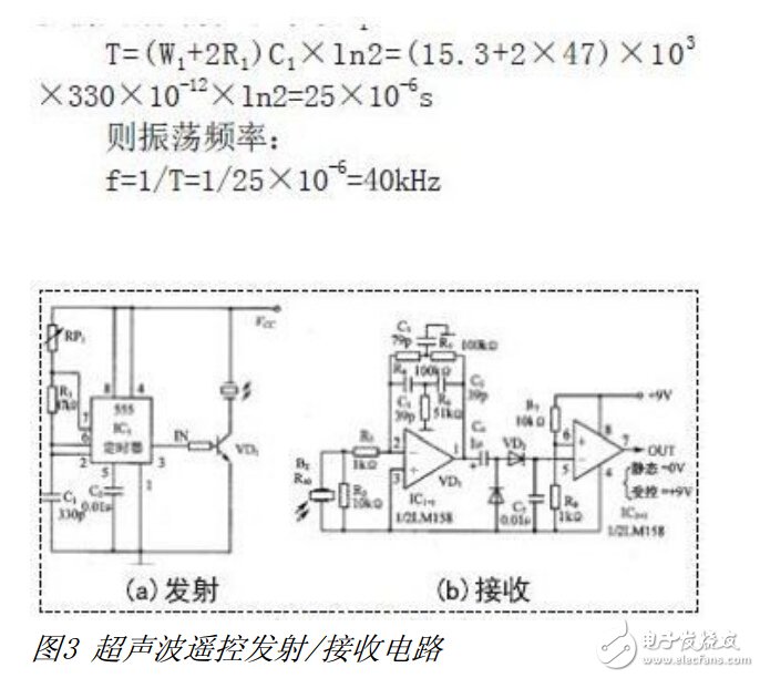
Adjusting W1 makes the oscillation frequency 40kHz, so the 555's 3 feet output 40kHz square wave, and the ultrasonic transmitting head T40 is driven by T1. The ultrasonic receiving head is R40, which must be used in pairs with T40. The receiving circuit type and working principle are the same as those in Figure 2. The difference is that ICl-1 in this figure constitutes a 40kHz double T network frequency selective amplification; C4, C5, VDl, VD2 are double voltage detection. The IC1-2 voltage comparator is the same as in Figure 2.
Generally, the ultrasonic remote control distance is 2m~10m, and the sensitivity and anti-interference performance can be considered by adjusting the gain resistors R3 and IC1-2 of ICl_l. This circuit can be used for anti-theft alarms or dangerous forbidden alarms.
Fourth, infrared remote control transmitting / receiving circuit
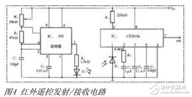
The infrared remote control transmitting and receiving circuit is shown in Figure 4. The transmitting circuit is basically the same as that of Figure 3. It is also a multi-vibrator composed of 555. However, the oscillating square wave drives the infrared transmitting tube D1 with an oscillation frequency of 35 kHz to 40 kHz. Set. The receiving circuit adopts the special integrated circuit CX20106, and the receiving center frequency f0=30kHz~60kHz, but it must be consistent with the transmitting end frequency, set by R4. When R4 takes 220kΩ, f0 is about 38kHz. The signal received by the infrared receiving tube PH302 is 1 Enter IC2, after amplification and demodulation, output by 7 feet. When debugging, first adjust the receiving circuit R4 to make the receiving frequency coincide with the transmitting frequency; then adjust R3 to make the circuit have appropriate sensitivity. The remote control distance of this circuit is 8m~10m, which can be used for anti-theft alarm; if the receiving output is connected to the electronic counter, it can be used for product quantity detection on the production line; if the receiving output drives the triode, then the triode drives the relay, and the relay drives the solenoid valve. The solenoid valve is used to control the faucet and constitutes an automatic water tap controller. The launcher is mounted near the tap, and the launcher can be either inductive or photoelectric. As long as the hand is close to the tap, the tap valve can be opened. Of course, an automatic hand dryer can also be made.
Handheld Fan Mini Portable Fan Powerful Personal Fans Speed Adjustable Battery Operated Type-C Rechargeable Eyelash Fan for Kids Women Men Indoor Outdoor Travel Cooling.
Mini Type-C Rechargeable Fan] cooling desk fans are built with 1200mAh rechargeable lithium battery, 3 adjustable speeds, fully charges in 3 hours, wireless working time 3-10hours. The lanyard design frees your hands and perfect for traveling
[3 Adjustable Speed & Enjoy Cool Summer]3 Adjustable Speed Level -- natural wind/cool wind/strong wind, just adjust the appropriate fan speed by pressing the power button repeatedly. Equipped with 3pcs fan blades which are made of ABS material, strong and durable produces a strong and soft airflow. Never worry about the outdoors even the temperature is so high. Just enjoy your cooling summer with this must-have
[Convenient design of portable fan]The mini fan weighs only 90 grams, That you can hang it around your neck with a lanyard without any pressure. Even if your child uses it, it will not bear weight pressure. You can put it in a backpack or handbag or even in your pocket when traveling outdoors. This simple and compact design is particularly suitable for summer travel or outdoor sports.
[Rechargeable Battery & Energy Source]The Type-C electric fan can be recharged with Type-C charger, laptop, computer, power bank, car power ban and other Type-C enable devices. A happy and lasting family journey
[Perfect Gift & After-sales]You can get a portable rechargeable fan, a Type-C cable, a lanyard, a fan stand and a User guide in the package. It's definitely a perfect gift idea for your families, friends, or your loved ones.
Rechargeable Small Pocket Fan,Handheld Mini fan, 3 In 1 Portable Type-C Mini fan
Shenzhen Focras Technology Co.,Ltd , https://www.focras.com