Emitter follower | | The emitter follower (also known as emitter follower, referred to as emitter follower or follower for short) is a common-collector circuit. See the figure below. It inputs the signal from the base and outputs the signal from the emitter. It has the characteristics of high input impedance, low output impedance, and the phase of the input signal and the output signal are the same |  | 1. The main index and calculation of the radio follower | 1. Input impedance From the circuit in the above figure (b), the input impedance from the end of 1, 1` to the right is: Ri = Ui / Ib = rbe + (1 + β) ReL
In the formula: ReL = Re // RL, rbe is the input resistance of the transistor. For low-frequency low-power tubes, its value is: rbe = 300 + (1 + β) (26 mV) / (Ie mV)
In the circuit of (b) above, if the input impedance from the b and b 'ends to the right is Ri = Ui / Ii = Rb // Rio. As can be seen from the above equation, the input impedance of the transmitter-follower is higher than that of the common emitter The input impedance rbe of the pole circuit is high (1 + β) times.
2. The output impedance will be Es = 0, and the output impedance from the e and e 'in the above figure (C) is: Ro = Uo / Ui = (rbe + Rsb) / (1 + β), where Rs = Rs // Rb,
If the output impedance from the output terminal 0, 0 'to the left is Ro = Ro // Reo
3. The voltage amplification factor is obtained according to the equivalent circuit of (b) above: Kv = Uo / Ui = (1 + β) Rel / [Rbe + (1 + β) Rel],
In the formula: Rel = Re // RL, when (1 + β) Rel >> rbe, Kv = 1, usually Kv <1.
4. The current amplification factor is calculated according to the equivalent circuit of (b) above: KI = Io / Ii = (1 + β) RsbRe / (Rsb + Ri) (Re + RL)
In the formula: Rsb = Rs // Rb, Ri = rbc + (1 + β) Relo Generally, the emitter follower has current and power amplification effect. | | Second, the practical circuit of the follower | | The following figure is a circuit used by a high-frequency amplifier. The signal is output by a coaxial cable. The characteristic impedance of the cable is generally 50 ohms or 70 ohms, so the impedance conversion must be achieved through the follower BG2. |  |
Figure 2 is a bootstrap follower, its characteristics are:
1. Bootstrapping Because the potential at the lower end of R3 rises with the rise of the potential at the upper end, it is called a bootstrap. The bootstrap effect makes the AC voltage drop across R3 zero. Therefore, for AC, R3 is equivalent to an open circuit, thereby avoiding the defect that the bias circuit reduces the input impedance.
2. High input impedance In order to increase the effective input impedance of the transistor as much as possible, BG1 and BG2 are used to form a composite tube circuit. At this time, β = β1β2, which greatly increases the total input impedance. Because the input impedance Ri = Rbe + (1 + β) Reo The input impedance of this circuit is 2 megohms, |
 |
| Figure 3 is a series-connected follower, its characteristics are: (1) similar to Figure 2, the AC voltage across R4 has a bootstrap effect; (2) BG2 uses a common base connection method, so that Ic2 has a constant current effect, A The AC impedance RAB at the two points of B and B is also greatly increased, thereby improving the input impedance of the follower. |
| Figure 4 is a complementary follower. The characteristics of the circuit are: (1) Because the two transistors supply the load current in turn, the power consumption of each tube is only about (12-20)% of the output power, and the efficiency is high; ( 2) Both transistors are output from the emitter, and their output impedances are basically the same, so the positive and negative half waves of the output waveform are symmetrical; (3) Since the input signal is coupled to the base of the transistor through BG3 or BG4, DC signals can be followed. Its following range is about ± 5 volts |
The world premiere of the technical zone! ROHM has developed the power supply IC "BD372xx series" for high-quality audio. A practical guide for the purchase of home wireless routers. Understanding the circuit diagram and working principle of the audio. Talking about the "frequency response curve" in the audio. Deep dismantling report of the M0pro speaker: both internal and external  Follow WeChat Interesting and informative information and technical dry goods  Download Audiophile APP Create your own personal electronic circle  Follow the audiophile class Lock the latest course activities and technical live broadcast Collect People collection share it: related suggestion Emitter coupled bistable circuit diagram Emitter coupled bistable circuit diagram Posted at 2010-03-29 17:44 • 323 times read 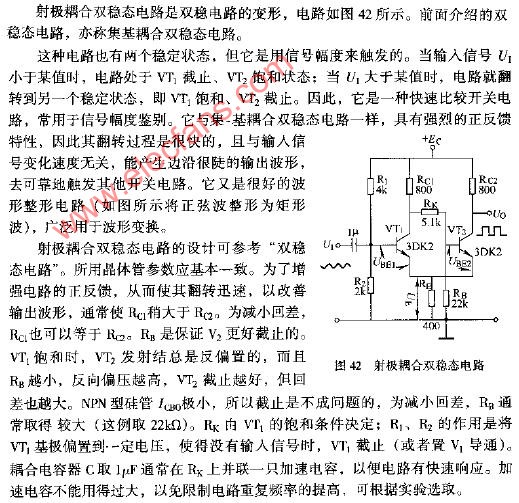 Characteristics and application of emitter output device Features and applications of emitter output & nb ... Posted at 2009-09-17 18:48 • 8502 views 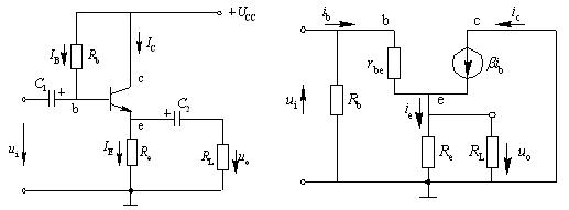 Emitter output characteristic measurement Emitter output characteristic measurement 1. Experimental purpose 1. By comparing with the common-emitter amplifier, master the main characteristics of the emitter output. 2. Study ... Published on 2009-03-08 14:21 • 1191 times read  Emitter follower experiment (including circuit diagram) Emitter follower Posted at 2008-09-27 16:47 • 9770 views  ![]() '+ data.username +' '+ data.username +'
|