High-performance technology for driving high-current LEDs in mobile phone camera light source applications
One of the more popular features in mobile phones is the built-in digital camera that captures high-resolution still and video images. As the wide-bandwidth 3G network continues to expand, the need for higher photo resolutions and new application areas, such as video conferencing, continues to increase the performance of integrated cameras. Enhanced camera performance also places higher demands on high-power white light sources when the camera is used indoors or in dim light. White LEDs have long been widely used in color display backlights, and have become the main source of light in camera-enabled mobile phones. White LEDs combine the performance required by today's handset designers: small size, large light output, and the ability to provide "flash" or continuous "video" scene illumination. Develop large output power LEDs specifically for integrated camera light sources. While these dedicated camera LEDs are ideal for lighting scenes, they are also another important factor in consuming battery power.
Design and implementation
From the designer's point of view, there are three main problems associated with driving high-current white LEDs: 1) providing efficient power; 2) adjusting LED current; and 3) ensuring that the LED is completely disconnected from the power supply when the camera source is turned off. High-current white LEDs have electrical characteristics similar to those of conventional diodes, but have a forward voltage of 3.4V or a "typical" 350mA forward operating current (see Table 1).
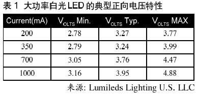
Larger LED currents ("flash" mode, 500mA - 700mA) cause higher forward voltages. Lower current ("flashlight" or "video" mode, 100mA~350mA) produces a lower forward voltage. The forward voltage also drops as the temperature rises, just as the forward voltage of any diode can produce hundreds of mV drift over the operating temperature range of the handset. Therefore, effectively providing power to the LED is very challenging, and the forward voltage of the LED may be higher or lower than the voltage of the lithium ion battery due to different operating conditions.
The most common solution for driving high current LEDs is to include a conventional step-up DC/DC converter with a resistor on the FB pin to GND to regulate the LED current. Based on this method, the output of the boost converter is connected to the anode of the LED, and the current of the LED flows from the cathode through the FB resistor to ground. The output voltage is boosted until the LED current reaches the value set by the FB resistor, that is, until the voltage drop across the FB resistor reaches the FB servo voltage. At the same time, this method provides precise adjustment, but it also has obvious disadvantages, the most serious of which is low efficiency. It is arguable that high efficiency is not important in short-term “flash†applications, but in “flashlight†or “video†mode, efficiency is more important due to longer operating time. Unfortunately, the boost converter performance in "Flashlight" mode is the worst.
In the boost topology, the input current is guaranteed to be greater than or equal to the output current. Since the LED forward voltage is typically lower than the battery voltage, even in the best case, the boosting efficiency is very low relative to a buck or full bridge topology. Moreover, since the boost converter does not properly control the input voltage below VIN, a relatively high value of the FB voltage is required to ensure that the regulator is always boosted. This is necessary to adjust the LED current under high VIN and low VLED conditions. Since ILED*VFB represents additional power consumption, the need for high VFBs further loses efficiency. In most high current camera light source applications, the PLED/PIN efficiency of a typical boost topology is between 60% and 70%. Because of the typical high current LED characteristics, an optimized LED driver should be suitable for buck and boost DC/DC conversion while adjusting the LED current in the current control circuit over a minimum voltage drop range.
If two or more parallel LEDs are used in one camera source, since there is a large variation in the forward voltage drop between any two LEDs, some additional devices that guarantee current matching accuracy are required. The most obvious way is to connect the LEDs in series so that the boost converter works well. However, if parallel connections are required, the solution must be able to provide independent current control for each LED. In either case, the current control circuit should produce as low a voltage drop as possible on the current sense resistor. Another complication in camera light source applications is the appearance of visible light from high current LEDs with low to microampere forward currents. There is no inherent LED disconnection, and a separate switch needs to be connected in series to the LED to ensure that no current flows through the LED when it is turned off.
The basic job of producing visible light with high-power LEDs is very simple, but it is very difficult to produce high-performance power and current control solutions in existing designs. In these applications, without a dedicated power IC to solve the above problems, battery life will still suffer. Linear Technology's LTC3453 is specifically designed to optimize efficiency, accuracy and control LED current in high current camera light sources (see Figure 1).
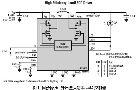
The LTC3453 utilizes a synchronous buck-boost power supply configuration and a programmable low-dropout current source to regulate the LED current. The device automatically switches between synchronous buck, synchronous boost, and four-switch buck-boost mode based on VIN and LED forward voltage. Each current source has its own independent control loop that regulates current at very low LED pin voltages to reduce power consumption. True LED disconnection can be achieved by turning off the current source. Four LED current sources (LED 1 to LED 4) can be used with the LEDs connected in parallel, or together to drive a single large output LED. The overall efficiency is optimized by adjusting VOUT with the lowest voltage required to ensure that all current sources are in regulation. In a synchronous buck-boost topology, the efficiency of the "flashlight" mode can be greater than 90% over the entire lithium-ion battery and LED forward voltage range, which is 20% to 30% better than a typical boost solution.
Conclusion
As 3G networks enable mobile phones to have more new applications, this has increased the demand for device performance. New features that can affect the market (such as cameras integrated with built-in camera light sources) are rapidly changing in performance, and in general, the burden of the already overburdened battery is heavier. Devices such as the LTC3453 for high performance are important to meet the needs of mobile phone designers for fast-changing needs and have minimal impact on battery life in new applications.
Plug Adapter,Mini Plug Socket,Mini Travel Plug
Double USB Travel Plug,Single Country Plug Adapter Co., Ltd. , http://www.chtravelplug.com