Design scheme of a mini CNC engraving machine system
0 Preface
With the rapid development of art models, machining, tooling and other industries, the requirements for processing equipment are getting higher and higher, and the engraving machine has also developed rapidly as an important part of the above-mentioned industries.
At present, the traditional engraving machine is large in size, complicated in operation, and high in price. Not only special computers are required to carry specialized software, but also professional operators are required to control them. Traditional engraving machines are mainly used for mass production. For some engraving machine enthusiasts and mold designers, they want to use engraving machines to engrave their own designs. Traditional engraving machines are highly professional, costly and impractical. In addition, some conventional engraving machines need to manually position the engraving head by manually rotating the hand wheel in three directions, with low precision and low efficiency. There are also some high-end engraving machines that use software to initially locate the engraving head, but the equipment is expensive.
In view of this, a mini CNC engraving machine system has been carefully designed. The system is not only simple and convenient to operate, but also has accurate positioning accuracy and high efficiency.
1 overall design of the system
In order to meet the requirements of the mini CNC engraving machine system, the engraving and processing of patterns and characters can be completed on non-ferrous metal materials. An engraving machine system based on ATmega128 single-chip microcomputer is designed. The system includes stepper motor driver module, LCD12864 liquid crystal display module, keyboard operation board module, ATmega128 single-chip minimum system module, ultrasonic sensor, power supply, serial communication module, etc. It consists of several parts.
The system structure block diagram is shown in Figure 1.
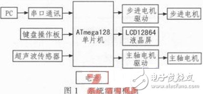
In the design of this system, the ATmega128 MCU produced by ATMEL Company is used as the main control chip. The MCU belongs to the AVR series MCU. It has 128 kB program memory and generates PWM wave module to facilitate the control of stepper motor and spindle motor. Among them, the PC is used to realize the interpretation of the G code of the workpiece by using MACH3 software, realize the conversion of the relevant data format, and then download it to the control board of the ATmega128 microcontroller as the main control chip through the serial communication module. Since the initial positioning of the engraving head is required before the engraving machine works, the button operation panel is designed in the system, and the preliminary positioning of the engraving head can be completed by the operation of six buttons of up, down, left and right, front and back, etc. on the button operation panel. Increased processing efficiency and material savings. The system also designed LCD12864 liquid crystal display, which is convenient for observing the coordinates of the engraving head and the processing time. For the control of the stepper motor on the three axes, the PWM wave generated by the ATmega128 microcontroller with the PWM module controls the stepper motor driver, thereby achieving precise control of the three-axis stepping motor.
2 function module selection
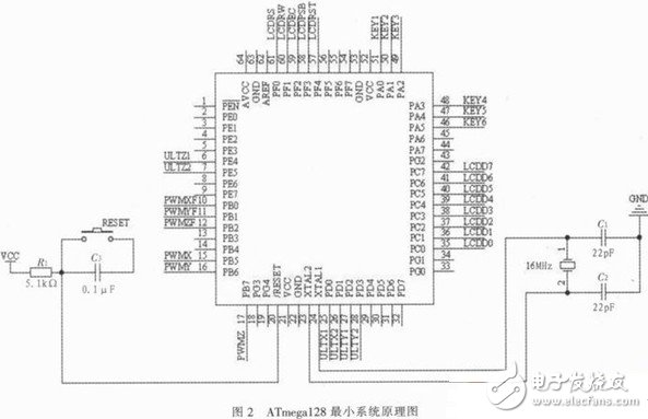
2.1 ATmega128 microcontroller minimum system module
ATmega128 is an 8-bit microprocessor designed by ATMEL. It has 128K bytes of in-system programmable Flash and 53 programmable I/O lines to meet the needs of many I/O ports in this design. Expand again. In addition, the device also has six resolution programmable PWM, which is convenient for generating standard pulse signals. There are also six external interrupt ports for anti-collision design. The minimum system schematic is shown in Figure 2.
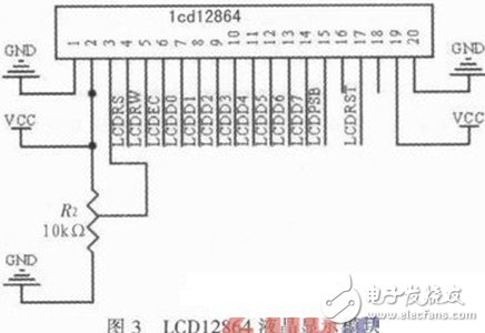
2.2 LCD12864 liquid crystal display module
In order to observe the coordinates of the engraving head position and the processing time during the machining, the system designed the LCD12864 liquid crystal display module. LCD12864 LCD display can display Chinese characters, uppercase and lowercase letters, and other various symbols to meet the design requirements. In this design, the ATmega128 microcontroller is used to control the LCD12864, in which the PC port is used as a parallel data port to transmit data to the LCD12864 parallel serial port. The PF port is selected for use as a control chip select, read/write, reset, and serial data transfer mode. LCD12864 liquid crystal display module is shown in Figure 3.
2.3 stepper motor drive module
The stepping motor is an electromagnetic mechanical device that converts an electric pulse signal into an angular displacement, and is a commonly used driving execution component of a numerical control system. The stepping motor must have a driver and a controller to work normally. The function of the driver is to perform loop distribution and power amplification of the control pulse, so that the stepping motor windings are energized in a certain order to control the rotation of the motor.
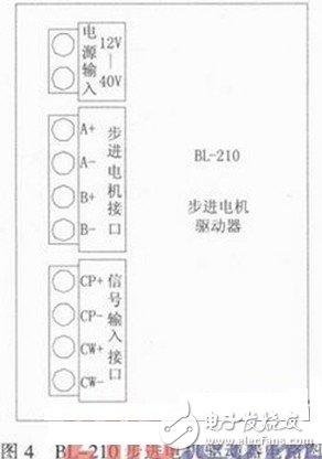
In the design of this system, BL-210 is used as the driver of stepping motor. The driver realizes high frequency chopping and constant current driving. It has strong anti-interference, high frequency performance, high starting frequency, control signal and internal signal. It realizes photoelectric isolation, current selection, simple structure, stable operation, good reliability and low noise. It can drive all stepping motors below 1.0 A. In addition, the number of subdivisions can be selected (1/2, 1/4, 1/8), and the corresponding microstep angles are (0.9°/STEP, 0.45°/STEP, 0.225°/STEP). The circuit diagram of the BL-210 stepper motor driver is shown in Figure 4. A+, A- connect to stepper motor A phase. B+, B- connected to stepper motor B phase. CW-signal transmission, and vice versa. The CP-signal controls the speed of the stepper motor. The PWM wave generated by the ATmega128 microcontroller is input from this port. When the PWM wave frequency is high, the stepper motor speed is faster, and vice versa. CP+ and CW+ are the common male ends of the input control signals, and both are connected to a high level.
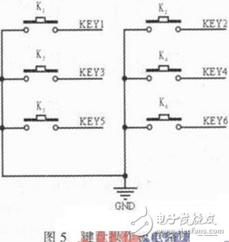
2.4 Keyboard Operation Panel Module
Before the engraving process, we have to preliminarily position the engraving head of the engraving machine so that the engraving head is in an ideal initial machining position. The main purpose of this is to save raw materials and improve processing efficiency. In this design system, six buttons, such as up and down, left and right, and front and rear, are designed. These six buttons are connected to the PA port of the single chip microcomputer. Through the operation of these 6 buttons, we can complete the positive and negative rotation of the three-axis stepping motor, thus completing the preliminary positioning of the engraving head of the engraving machine. The circuit diagram of the keyboard operation panel is shown in Figure 5.
3 software design
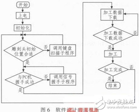
In the software design of this system, AVR Studio is selected as the embedded development environment, and C is used as the writing language. The AVR Studio integrated development environment includes features such as the AVR Assembler compiler, AVR Studio debug features, AVRProg serial, parallel download capabilities, and JTAG ICE emulation. With these features, we can edit the source code online and run it on the AVR device to facilitate development by AVR microcontroller developers. As a high-level language, C language is highly efficient and easy to understand. In the programming process, the modular writing idea is adopted, and the whole software system is composed of serial communication module, PWM wave module, LCD12864 liquid crystal display module, keyboard scanning module, and ultrasonic sensor causing interruption. The program flow chart of system software design is shown in Figure 6.
4 anti-collision design
Practice production shows that the engraving machine often has a collision accident during work. There are many causes of collisions, such as incorrect G code generated by the host computer, improper operation of the initial positioning of the engraving head, and incorrect parameter setting. Once the engraving machine collides, the engraving knife breaks, and the stepping motor burns down, and even the main board is damaged. The occurrence of such an accident will not only cause unnecessary economic losses, but also delay work and production. Therefore, it is also necessary to design a device in the control system to avoid such a collision accident.
In order to solve the above problem, in this design, an ultrasonic sensor is mainly installed at each end of each ball screw. When the moving platform in the three-axis direction moves to the edge quickly, the ultrasonic sensor will generate a signal and transmit this signal to the control board, and the control board will stop generating the pulse signal, and the stepping motor stops working.
5 Conclusion
As a typical mechatronics equipment, the engraving machine requires high precision and stable system. This program adopts ATmega128 in AVR series products as the main control chip of the system, which has stable performance and convenient use. In the scheme, the design of the button operation panel of the system preliminarily locates the engraving head, which is convenient and efficient. Through the experiment of the self-made mini CNC engraving machine, the control effect is stable and meets the needs of the design.
High-inquiry Portable Power Station & Solar Panels
Portable Power Stations & Solar Panels,Foldable Portable Solar Panels,Portable Solar Panels,Mobile Laptop Charging Station
Guangzhou Fengjiu New Energy Technology Co.,Ltd , https://www.flashfishbatteries.com