Power magnetic induction wireless charging system, MCU has a lot to do!
Microcontrollers (MCUs) play a pivotal role in magnetic induction wireless charging systems. The magnetic induction wireless charging system uses the coupling between the transmitting end and the receiving end to generate power, so the loss problem is serious. Developers can use the voltage and current in the induction coil of the microcontroller to adjust the inverter parameters to ensure the performance of the wireless charging system.
Technology, software and hardware continue to innovate, enabling devices such as tablets, smartphones, cameras, and global positioning systems (GPS) to grow rapidly. These devices are primarily battery-powered, and new features continue to increase, such as touchscreens, widescreen displays, etc., while devices can run applications over the Internet, all of which increase power consumption.
However, the size and performance of the battery are far less powerful than the increase in power demand, so the battery needs to be recharged frequently. Consumers still need to spend a lot of effort carrying chargers and a lot of cables to charge the batteries frequently. Although it holds advanced equipment, it feels like you are still living in the Stone Age. For these reasons, scientists are working hard to research new ways to charge wirelessly without the need for cumbersome device accessories for easier and more convenient charging. It sounds sci-fi, but it has now become a reality.
In fact, wireless transmission of energy is widely used in many fields, such as radio waves, microwaves, etc., which have been applied in the fields of wireless communication, satellite, radio, television, and the like. These waves are transmitted from the transmitter and propagate in all directions. When the antenna is reached, the antenna changes the frequency of these waves, so only a small fraction of the energy reaches the receiver. If the transfer of electrical energy is also using this method, it will become very inefficient. Before the advent of the microprocessor (MPU), the concept was affected by inefficiencies and lack of control, as well as security and other issues.
Most of today's wireless charging technologies use inductive coupling for power transfer. Although other methods such as laser diodes, microwave beams, etc. can wirelessly transmit power, none of them are discussed in this article.
Inductive coupling produces a current magnetic field
Inductive coupling (Figure 1) is being used in a variety of motor applications, using magnetic fields that generate a variety of moving currents. Basically, the principle of the transformer is to change the electrical energy between the two inductors by magnetically coupling them. For details, refer to the electromagnetic law of the Faraday invention. When the mobile device is operating on an alternating current, the electrical energy sensed in the receiver naturally alternates and changes to alternating current.
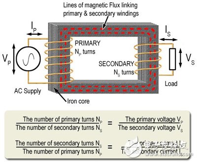
Figure 1 Inductive coupling diagram
Electromagnetic induction is proportional to the current and voltage strength and frequency within the conductor that produces the magnetic field. The higher the frequency, the stronger the induction. Energy is transmitted from conductors that generate magnetic fields (primary) to other conductors and magnetic field shocks (secondary) occur. Part of the energy in the primary conductor is transmitted to the secondary conductor by induction, and the energy is rapidly reduced along the primary conductor.
High-frequency currents do not pass through long-distance conductors, but they quickly change their energy to adjacent conductors through sensing. The higher inductance produced by higher frequencies is a good indication of the significant difference between high frequency propagation and low frequency propagation in AC systems. The higher the frequency, the more obvious the inductive effect and the transmission of energy through the space between the circuits. The faster the energy is reduced, and the current disappears along the circuit, the more local phenomena.
Electrical equipment should not be magnetically coupled by air because air has poor permeability and can lead to inefficiencies. But for mobile applications, air is still the medium of choice when using highly permeable cores that can make equipment heavier. By using resonance technology, designers can increase energy more efficiently, allowing it to travel through airborne media over short distances.
Wireless charging is much more complicated because it places high demands on the transmission and reception of energy, communication and control, and requires more complex and advanced circuits, so it is necessary to establish new standards for wireless transmission of energy.
Figure 1 shows an ideal transformer, a transformer with no power loss, in which the Volt Ampere = two-stage volt-amperes. Although the transformer is very efficient in practical applications, power loss still occurs because not all of the magnetic flux generated by the primary coil is connected to the secondary coil. The following three conditions can cause power loss in the transformer:
. Copper loss
Copper loss can also be called coil loss or I2R loss, because coils made of other metals can also wear out. These losses are caused by overheating of the copper wire coil, because the copper wire has resistance and consumes a certain amount of power.
The power dissipation generated by the transformer coil can be calculated by calculating the current and resistance in the coil. The formula is P = I2R. This formula explains why copper loss is called the cause of I2R loss. In order to minimize losses, the resistance in the coil must be kept to a minimum, so coils with a moderate cross-sectional area and low resistivity are used.
. Hysteresis loss
Whenever the alternating current is reversed (once per cycle), the tiny "magnetic domains" with the core material are also reversed. These physical changes in the core material also consume a certain amount of energy.
The amount of energy loss depends on the "magnetoresistance" of the core material. For large power transformer cores, hysteresis loss may be a big problem, which can be achieved by using special low reluctance "grain orientation" steel as the core material. Overcome this problem.
. Eddy current loss
Because the iron and steel cores are both electrical and magnetic, the change in current in the primary coil tends to create an electromagnetic wave (EMF), as well as in the secondary coil. The current induced in the core will impede the change of the magnetic field in the core, so the eddy current must be kept as low as possible by separating the metal core onto the sheet or lamination (LaminaTIons) and passing through the insulating varnish and oxide. Keep each laminate separate from the others. The core being laminated greatly reduces the formation of eddy currents and does not affect the performance of the core.
08*16 2835 Led Neon Flex,Neon Flexible,Neon Flex Light,Neon Flex Led Strip
NINGBO SENTU ART AND CRAFT CO.,LTD. , https://www.lightworld-sentu.com