Fixed-gain operational amplifier simplifies filter design-Fixed-Gain O
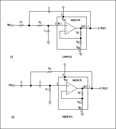
Simple second-order filters meet many filtering requirements. A low-order low-pass filter, for example, is often adequate for anTIaliasing in ADC applicaTIons or for eliminaTIng high-frequency noise in audio applicaTIons. Similarly, a low-order high-pass filter can easily remove power-supply noise. When you design such filters with built-in gain, fixed-gain op amps can save space, cost, and time. Figure 1 illustrates the use of fixed-gain op amps in building second-order low-pass and high-pass Sallen-Key filters. Filter "cookbooks" are useful in designing these filters, but the cookbook procedures usually break down for a given response, such as Butterworth, if the gain set by RF and RG is greater than unity. What's more, the cookbook component-value formulas can yield unrealistic values ​​for the capacitors and the resistors.

Figure 1. Sallen-Key filters use fixed-gain op amps to realize a second-order Butterworth response.
Butterworth filters, for example, offer the flattest passband. They also provide a fast initial falloff and reasonable overshoot. You can easily design such filters using the table below with the following equations: R2 = 1 / (2πfC √) and R1 = XR2.
Butterworth-Filter-Design Criteria
| Gain | Low-Pass X | High-Pass X |
| 1.25 | * | 1.372 |
| 1.5 | 2 | 1.072 |
| 2 | 0.5 | 0.764 |
| 2.25 | 0.404 | 0.672 |
| 2.5 | 0.343 | 0.602 |
| 3 | 0.268 | 0.5 |
| 3.5 | 0.222 | 0.429 |
| 4 | 0.191 | 0.377 |
| 5 | 0.15 | 0.305 |
| 6 | 0.125 | 0.257 |
| 7 | 0.107 | 0.222 |
| 9 | 0.084 | 0.176 |
| 10 | 0.076 | 0.159 |
| 11 | 0.07 | 0.146 |
| 13.5 | 0.057 | 0.121 |
| 16 | 0.049 | 0.103 |
| twenty one | 0.038 | 0.08 |
| 25 | 0.032 | 0.068 |
| 26 | 0.031 | 0.066 |
| 31 | 0.026 | 0.056 |
| 41 | 0.02 | 0.043 |
| 50 | 0.017 | 0.035 |
| 51 | 0.017 | 0.035 |
| 61 | 0.014 | 0.029 |
| 81 | 0.011 | 0.022 |
| 100 | 0.009 | 0.018 |
| 101 | 0.009 | 0.018 |
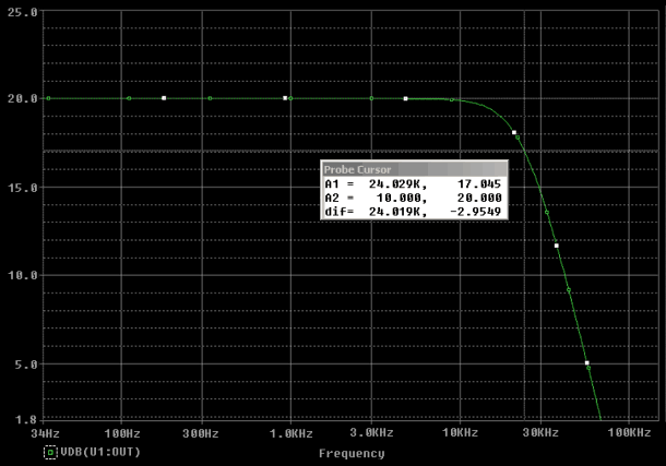
For a gained filter response, the use of a fixed-gain op amp reduces cost and component count. It also decreases sensitivity, because the internal, factory-trimmed, precision gain-setting resistors provide 0.1% gain accuracy. To design a second- order Butterworth low-pass or high-pass filter using a fixed-gain op amp, follow these steps: Determine the corner frequency fC. Select a value for C. For the desired gain value, locate X under the proper column heading in the table . Calculate R1 and R2 using the equations. Choosing C and then solving for R1 and R2 lets you optimize the filter response by selecting component values ​​as close to the calculated values ​​as possible. C can be lower than 1000pF for most corner frequencies and gains. Fixed-gain op amps come optimally compensated for each gain version and provide exceptional gain-bandwidth products for systems operating at high frequencies and high gain. Suppose, for example, you must design a low-pass filter with a 24kHz corner frequenc y and a gain of 10. Step 1 is complete (fC = 24kHz). Next, complete Step 2 by selecting a value for C, say, 470pF. In the table, note that X = 0.076 for a low-pass filter with a gain of 10. Substitute these values ​​in the equations: R2 = 1 / (2π fC √) = 1 / (2π × 24kHz × 470pF × √) = 51kΩ, and R1 = XR2 = 0.076 × 51kΩ = 3.9kΩ.

Figure 2. Using the circuit values ​​in the text, a simulation of the circuit in Figure 1a produces this Butterworth response.
A similar version of this article appeared in the July 6, 2000 issue of EDN.
Dual-band WiFi module refers to the WiFi module that supports both 2.4GHZ and 5GHz bands. The dual-band WiFi module can operate in the 5Ghz band, which is much cleaner and can easily avoid interfering with each other. The advantage of 2.4G is that it has good ability to penetrate the wall, and the disadvantage is that it is easy to be disturbed. The advantages of 5G are strong anti-interference ability, wide band width, high throughput rate, and strong scalability, but the disadvantage is that 5G is only suitable for indoor small-range coverage and outdoor bridge, and the attenuation effect of various obstacles on it is much larger than 2.4g.
Dual-band WiFi module has a stronger and more stable Wifi wireless signal, higher transmission speed, and can make wireless devices more power-saving, to meet the future high-definition and big data wireless transmission needs.
When selecting a dual-frequency WiFi module, we should pay attention to these parameters of the WiFi module: size, package, frequency range, data rate, transmission rate, transmission distance, communication interface, power supply voltage, antenna interface, etc.
Dual frequency WiFi module can well meet the functional needs of users, increase the competitiveness of the product, while the WiFi module is easy to use, can shorten the user product development cycle, speed up the product market! Users can make choices according to actual needs!
Choosing a dual-band WiFi module may need to pay attention to the following points:
(1) Consider the transmission power of the dual-frequency WiFi module
The transmitting power of the WIFI module is generally about 18dBm, and the transmitting power of the high-power WIFI module is about 28dBm.
(2) Transmission rate
Consider whether the dual-band WiFi module supports MIMO technology (that is, allows multiple antennas to send and receive multiple spatial streams simultaneously)
(3) Consider the application interface that dual-band WiFi modules can provide, which is also very important.
(4) According to the requirements of the application scenario to choose the dual-band WiFi module, not the higher the configuration, the better, the application is good, excess waste!
Dual Band Router Module,Dual Band Wifi Module,Dual Band Router Embedded Wifi Module,Gigabit Ethernet Router Module
Shenzhen MovingComm Technology Co., Ltd. , https://www.szmovingcomm.com