Electric vehicle battery pack battery management and status detection
Electric vehicle battery pack battery management and status detection
Abstract: The working state of the battery pack of electric vehicles mainly refers to the changes of the five parameters of the terminal voltage, working current and temperature of each battery during operation. The detection of the working state of the battery usually has a centralized detection method and a distributed detection method. The idea of ​​"partial" centralized and "whole" distribution is used to divide the battery into several groups. The "bridge capacitance" technology is used to solve the problems of reference point selection and isolation of the tested battery and the testing equipment in the battery terminal voltage detection, forming a centralized / distributed detection method with complete isolation. After testing, the detection method of voltage, current and temperature acquisition function is normal, the data is accurate and reliable.
Keywords: electric vehicles; automotive engineering; batteries; centralized / distribution detection
0 Introduction Battery technology is one of the core technologies of the next generation of vehicles-electric vehicles. Accumulators are complex electrochemical systems. A lot of research has been conducted on battery management technologies at home and abroad, and many achievements have been made. It is generally believed that the battery management system mainly has the following functions: battery state parameter collection (including temperature, voltage, current, etc.); accurate estimation of battery state of charge (SOC); early diagnosis of unhealthy batteries; safe operation of battery packs Comprehensive monitoring, such as preventing overcharge and overdischarge of batteries, etc.
Since the battery pack of an electric vehicle is usually composed of dozens (hundreds) of single cells, the normal operation status of each single cell not only reflects the performance of the battery pack but also affects the capacity and Remaining energy. Practice has shown that during the operation of an electric vehicle, if it is not detected in time and the aging battery is found and adjusted, the capacity of the battery pack will become smaller and the life will be shortened, affecting the efficient and safe operation of the entire battery pack.
The detection of battery working status is completed by the battery management system (BMS), and other functions of the battery management system (including the calculation of remaining energy) are based on the detection of battery working status. The state detection method is of great significance to the development of electric vehicles.
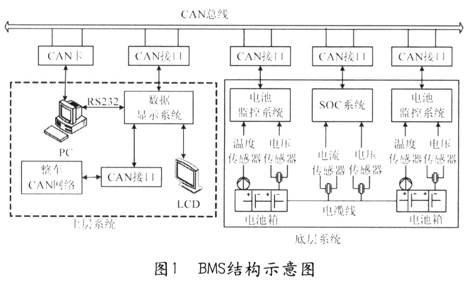
l Basic structure of BMS The schematic diagram of BMS structure adopted by the electric vehicle (EV No. 3) developed by Hunan University is shown in Figure 1. The BMS consists of three parts: battery monitoring system, battery nuclear power state, (SOC) system, and data display system. The sensor, battery monitoring system and SOC system form the bottom layer system, and the data display system is the upper layer system, and the internal CAN bus communicates between the systems.
2 Detection method of the working state of the battery pack The battery pack of the electric vehicle generally works in series, the working current is the same as the single battery, the detection is easier, and the detection of the terminal voltage is more troublesome. If only the terminal voltage of the battery pack is detected, the method is very simple, just connect the detection circuit to both ends of the battery pack, but this will not work, because although the total operating voltage can be obtained, the specific monomer cannot be judged The terminal voltage of the battery, and as long as there is a problem with one battery, it will affect the normal operation and performance of the entire battery; in addition, the detection circuit requires high accuracy. The normal operating range of the voltage of a single battery is relatively small. For example, the termination voltage of a 12V lead-acid battery is about 10V, and the voltage change range is between 2 and 3V. The detection circuit can detect a 1V change with only 10% accuracy. . If 24 12V lead-acid batteries are connected in series, the rated voltage is 288V, the end-of-discharge voltage is 240V, and the normal range of voltage is 48V. If the terminal voltage of a battery drops to 9V, then it is reflected in the total voltage of 285V, only changed About 1%. It can be seen that the accuracy of the detection circuit must be at least 1% or more to detect the change of a few volts. It is difficult to detect the slow changes of the single battery in the entire battery test, including the aging of the single battery and the cumulative effect caused by the consistency of the single battery. The entire set of tests cannot detect the actual capacity of the battery and the battery pack, and cannot screen out the aging batteries.
The practical method is to test every single battery. But for the battery packs formed in series, the main problems encountered when automatically detecting the terminal voltage of each single cell are the choice of measurement reference point and the electrical isolation between the detection circuit and the battery pack being tested. The selection of the potential reference point not only affects the measurement accuracy as described above, but also places high requirements on the measurement range of the measurement circuit. The isolation of the detected battery pack and the detection circuit not only involves the safety of the system but also affects the complexity and realizability of the detection circuit. At present, the main methods used are distributed detection and centralized detection.
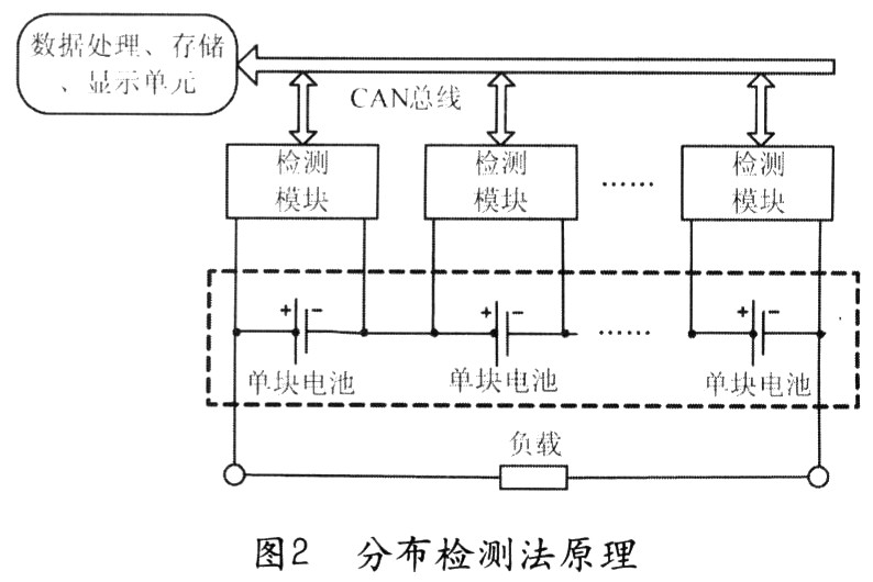
1) Distributed detection method The so-called distributed isolation detection technology is to modularize and localize the detection of single cell voltage and temperature, and then collect the data detected by these detection modules through certain communication means, and finally process them uniformly. The purpose of this is to solve the problems of centralized detection methods. The schematic diagram is shown in Figure 2.
Its main advantages are:
(1) The connection is simple, the multi-way switch is omitted, and the performance is reliable.
(2) The measurement accuracy is high, which is more in line with the development trend of the CAN bus of automotive electrical appliances.
(3) The distributed module solves the reference point problem, and the bus communication method (using optocoupler devices) solves the problem of isolation between the main controller and the battery pack.
But the application of distributed detection technology must also solve the following problems:
(1) Because the detection module directly draws power from the battery under test, it is not conducive to energy saving and safety.
(2) When there are many batteries, the number of modules is also large, which increases the cost and complexity, and requires a higher load capacity of the communication bus.
From a functional point of view, the detection module is mainly composed of two parts: a detection sub-module and a communication sub-module. The detection sub-module needs to complete data collection and conditioning tasks, while the communication sub-module needs to communicate information with the main control circuit, receive instructions from the main control circuit, and upload the detection data provided by the detection sub-module.
Because the development direction of automobile electrical appliances is to adopt CAN bus technology, therefore, the CAN bus connection should be used between the communication sub-module and the main control circuit.
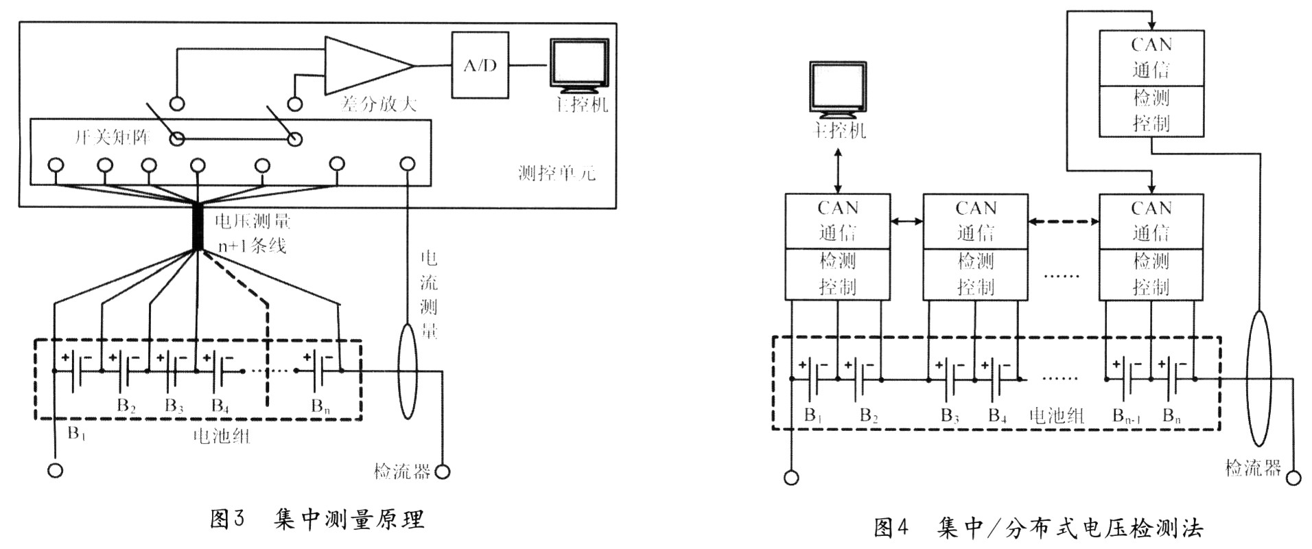
2) Centralized detection method The centralized detection method (see Figure 3) uses a set of detection circuits to detect each single cell in a time-sharing manner. The detection technology is relatively intuitive. In order to detect the voltage of each battery, the voltage signal of each battery needs to be introduced into the detection device (if the battery pack is composed of n single cells, n + 1 detection lines need to be led), using multi-channel switching The technology, that is, the voltage signal of the multi-cell battery is switched to the same differential amplifier through a switching device (relay), and after signal processing, an A / D converter is used for sampling. "Switching" dynamically changes the reference point to ensure that each measurement is the terminal voltage of a single battery; and the differential input ensures that the battery pack and the detection circuit do not share the ground. Although they are not fully isolated, they are more common. Ground connection should be safe. The detection of battery temperature can generally use digital or analog temperature sensors. Because the temperature measurement process is not electrically connected to the battery pack and the technology is relatively mature, so this article will not repeat them. In addition, due to the large current required by electric vehicles (tens to hundreds of amps), the detection of the charging and discharging current of the battery pack is generally implemented by a non-contact current sensor or a transmitter.
The main disadvantage of this method is that there are more signal lines, which increases the difficulty and complexity of wiring, affects the test accuracy, and reduces reliability.
3) Centralized / distributed detection method In order to overcome the shortcomings of the distributed detection method and the centralized detection method, we propose the detection ideas of "local concentration" and "overall distribution", that is, all batteries are divided into several groups, and each group uses a detection module For "centralized" detection, the entire system is made up of several detection modules connected via CAN bus. In short, the essence of the centralized / distributed detection system is that the detection unit is partially modularized and localized, and the data is transmitted by the bus. In addition to the advantages of the first two methods, centralized / distributed detection has the following main advantages: it strengthens the flexibility and expansibility of system formation; increases the reliability of the system; and has a high cost performance.
For lead-acid batteries, due to their high cell voltage, large volume, and small number, a detection module can be assigned to every 2 or 4 batteries. For a battery pack such as a lithium battery, which has a relatively low cell voltage and a small volume but a large number, 2 to 8 batteries can be divided into a group. Figure 4 is a block diagram of centralized / distributed detection.
In order to reduce costs, reduce volume, and simplify circuits, the battery detection module should be completed by a single-chip microcomputer. The main conditions for the selection of single chip microcomputer are: at least 4 A / D converters with a precision of more than 10 bits (because a battery requires at least 2 detections of voltage and temperature); with a CAN bus controller.
We chose the MICROchip company's PICl8 series for the front-end detection module. The PIC18F248 / 258 and PIC18F2585 / 2680 of this series are 28-pin dual in-line packages. The PIC18F248 / 2587 has five 10-bit A / D converters; the PICl8585 / 26801 has eight 10-bit A / D converters. And with nanowatt power management technology to further reduce the power consumption of the chip. PICl8F2585 / 2680 also has online serial programming technology, which allows the microcontroller to be programmed after it is embedded in the circuit board, which provides great convenience for use.
In our project, 24 12V lead-acid batteries were used, which were divided into three groups and placed in the car. There were 6 batteries in the luggage position on each side, 12 batteries in the rear luggage position, and 2 batteries shared One detection module, that is, one detection module collectively detects the status of 2 batteries. Finally, it should be noted that since the temperature sensor has no electrical contact with the battery, the temperature detection part is not shown in the detection schematic diagram, but each detection module has a temperature detection function.
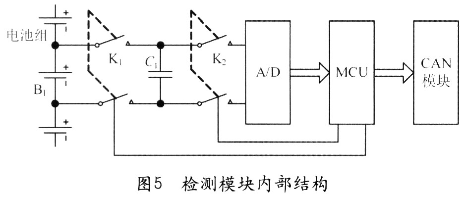
In order to overcome the problem that the module continues to draw power from the battery, we will supply power to all modules in a unified manner, controlled by a main switch. This involves the isolation of the power supply circuit and the battery. To solve this problem, we use the "bridge capacitance" technology. Figure 5 is a block diagram inside the module. The working principle of the "bridge capacitor" is this: MCU first closes the double-pole single-throw switch K1, then the battery charges the capacitor C1, because the time constant is very small, the capacitor terminal voltage quickly reaches the battery terminal voltage; then the MCU is disconnected K1 closes K2, the terminal voltage of C1 can be collected from A / D, that is, the terminal voltage of the battery; finally the MCU disconnects K2. Thus completing a collection task. In addition, when the module is not powered, the two sets of switches are open, the module will not take power from the battery. It can be seen that this method not only solves the reference point problem, but also completely isolates the battery from the detection circuit. Its main disadvantage is that each module adds two sets of controllable switches. The controllable switch uses optocoupler relay AQW212. The cost of the module is about 200 yuan, which is very suitable for the use of electric vehicles. Each detection module uploads the data to the host computer through the CAN bus. It is processed and displayed by the host computer for the driver's reference.
3 Conclusion (1) The centralized / distributed detection method is used to detect the battery pack parameters, which overcomes the problems of the centralized and distributed detection methods, and is more suitable for the detection of electric vehicle battery packs.
(2) Using the "bridge capacitance" technology to transfer the collected battery voltage signal can effectively solve the isolation problem between the battery and the detection circuit.
(3) Through the test on 24 12V lead-acid battery packs, the centralized / distributed detection system composed of 12 detection modules and a main control machine works normally, and the detection data of voltage, current and temperature are accurate and reliable. It shows that the centralized / distributed detection method is feasible and has high application value.
R18 Bone Conduction Headset,Waterproof Wireless Headphones,Wireless Sports Earphones Headphone,R18 Sport Headset
Shenzhen Lonfine Innovation Technology Co., Ltd , https://www.lonfinesmart.com