Protect data lines and power lines in automotive electronic systems
Foreword Today, the proportion of automotive electronic equipment in the entire vehicle is quite large. While these electronic modules bring comfort and safety to automotive users, at the same time, the analysis of the reliability of electronic modules in the automotive environment has created problems that cannot be ignored.
This article refers to the address: http://
Because electronic modules are sensitive to electromagnetic interference (EMI), electrostatic discharge (ESD), and other electrical disturbances (the car itself is the source of these hazards), care must be taken when using electronic modules in automotive environments. In response to the common electrical hazards of current automobiles, the International Organization for Standardization has issued several sets of electrical protection standards. Automakers and suppliers must consider these standards, and only by adding protective components to the electronic modules can they fulfill the primary responsibilities set out in these standards. For example, in-vehicle electronic modules must withstand electromagnetic interference and ESD transient voltages as specified by the two international standards ISO 7637-2 and ISO 10605.
Electrical hazards in automotive environments
The automotive environment itself includes many sources of electrical hazards. Various components of the car, such as ignition switches, relay contacts, alternators, fuel injectors, etc., can cause electrical interference such as electromagnetic interference and electrostatic discharge. Conductive hazards appear directly in the wire bundle; radiation hazards directly affect the electronic module. These electrical hazards from the automotive environment will affect the electronic modules in two ways: data lines and power lines.
Spread of electrical hazards
Transient events generated in the automotive environment may vary from low energy levels to high energy levels, and may also vary from high energy levels to low energy levels, accompanied by extremely high voltage slopes dV/dt. The main standards for these electrical hazards are ISO7637-2 and ISO10605, and sometimes the IEC61000-4-2 standard, as some manufacturers have been using the ESD standard before the release of the ISO10605 standard.
ISO7637-2 is a standard related to power line applications; ISO 10605 (some manufacturers use IEC61000-4-2) is a standard for all electronic module accessories such as potentiometers, liquid crystal displays, buttons and data line connectors.
Figure 1 briefly depicts the main surges on the ISO7637-2 and automotive power lines.
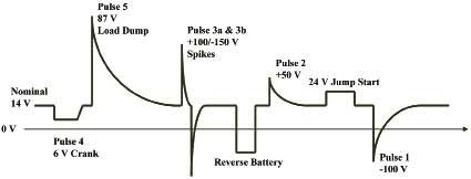
Figure 1 Main surges on the ISO7637-2 and automotive power lines
Data line and power line application
The limiting factors for data lines and power lines are different. Data line applications typically have low line capacitance limitations that are required for high speed data line functions, while data lines also require high ESD protection. Therefore, it is more difficult to choose a protection circuit that balances both low capacitance and high ESD protection.
On the other hand, although the power line application does not require low capacitance, it is not easy to find the most suitable protection component because the ISO7637-2 standard applies various pulses. For example, 甩 load surges and transient events generated by relay switches use different protection components.
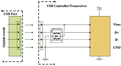
Figure 2 How to protect high speed data lines
Data line protection
Take the USB accessories of car audio equipment as an example to discuss the protection of USB. The contact portion of the USB interface may be affected by ESD transient events, so USB data must use a dedicated protection component. Because the data rate of the USB data line is usually very high (480Mb/s), in order not to reduce the strength of the normal working signal, it is necessary to use a low-capacitance protection component, while suppressing the ESD surge of ±25kV ESD ( ISO10605). Using the topology of Figure 2, a balance can be found between low capacitance and efficient ESD suppression.
The essence of this approach is to connect a protective component near the USB interface. It consists of several diodes with rail-to-rail construction and inherently low capacitance. The internal clamp device provides ±25kV ESD (ISO10605) protection for both data lines and protection for the Vbus power line.
Assume that the capacitance of each rail of the rail-to-rail protection device is 2.5 pF. The frequency response of this protection topology is predicted as shown in Fig. 3.
The cutoff frequency in Figure 3 is approximately 5 GHz, away from the normal operating frequency of the USB 480 Mb/s transceiver, so the USB transceiver can operate safely.
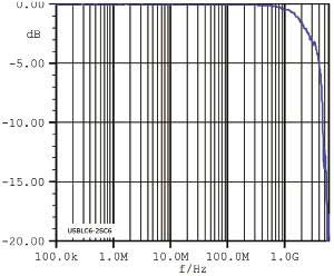
Figure 3 frequency response
There is also a way to check the effect of this rail-to-rail protection component on the normal operating mode of the USB protocol, which is to analyze the integrity of the signal data bits through the eye diagram response of Figure 4.
It is not difficult to see from Figure 4 that the integrity of the USB 2.0 signal is not greatly affected, so its transmission is safe.
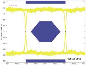
Figure 4 Eye Diagram Response with USB 2.0 Template
Another advantage of the rail-to-rail protection solution is the ability to suppress ESD surges that occur on the external interface when plugging in external components, such as car audio systems.
If you continue to use this 2.5pF internal capacitance rail-to-rail protection component, assuming an internal clamp voltage (Vbr breakdown voltage) of 6V, you can predict the air discharge response ESD ±25kV ISO10605 (150pF/330). When an ESD surge of +25kV is applied, the residual overvoltage on the electronic side of the module is approximately +35V; when an ESD surge of -25kV is applied, the residual overvoltage on the electronic side of the module is approximately 30V.
Power line protection
The power line protection of the vehicle module is another issue that needs attention in the automotive environment. This issue involves the ISO7637-2 standard.
For example, to meet the ISO 7637-2 standard, particularly the pulse requirements of 1, 2, 3a, and 3b in Figure 1, an in-vehicle module can be effectively protected using only one transient voltage suppressor (TVS).
The power line protection topology is shown in Figure 5.
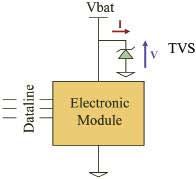
Figure 5 Electronic module power line protection topology
When subjected to the pulses of 1, 2, 3a and 3b in Fig. 1, the characteristics of the protection circuit are as shown in Figs. 6, 7, 8, 9, and 10.
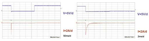 Figure 6 During the pulse 1 test Figure 7 is different during the pulse 1 test
Through the voltage and current on the TVS through the voltage and current on the TVS
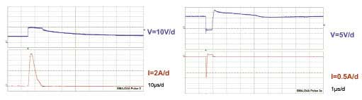
Figure 8 During the pulse 2 test Figure 9 during the pulse 3a test
Through the voltage and current on the TVS, the voltage and current through the TVS
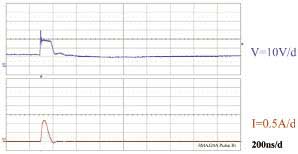
Figure 10 Voltage and current through the TVS during the ISO7637-2 pulse 3b test
The problem we have to solve is to determine the parameters of the protection components based on the surge to be eliminated. Taking the ISO7637-2 pulse 2 in Figure 8 as an example, it is easy to see that the clamp voltage on the suppressor is about 30V, the peak pulse current (Ip) is about 12A, and the current pulse duration (tp) is measured at Ip/2. It is 4μs. Therefore, it can be determined that the TVS must consume a maximum pulse power (Pp) of 360 W. All of these Pp, Ip, and tp values ​​are useful because they can help compare the peak pulse power versus the exponential pulse duration in the TVS datasheet to ensure that the TVS is within the limits of the application.
in conclusion
Taking SMAJ24A as an example, these parameters are extracted from the product data table and compared with the curve of Fig. 11. It is found that SMAJ24A meets the requirements of ISO7637-2 pulse 2 test and can withstand 360 W index pulse of 1.2 ms, which is much higher. For 4μs duration forced by ISO 7637-2 pulse 2 surge.
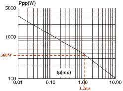
Figure 11 Peak pulse power vs. exponential pulse duration curve (Tj initial=25°C)
The automotive environment is the main source of electrical hazards, and electronic devices are increasingly susceptible to interference, so electrical hazards must be carefully considered when designing electronic modules. In order to ensure the safety of electronic modules and systems and to protect various electrical hazards generated inside the car, the use of protective components has become a common method.
Warning lights are generally used to maintain road safety. They are usually used in police cars, engineering vehicles, fire engines, ambulances, maintenance management vehicles, road maintenance vehicles, tractors, emergency A/S vehicles, mechanical equipment, etc., machinery, electricity, Control signals interlocking in electrical control circuits such as machine tools, chemicals, telecommunications, ships, and metallurgy.
For Warning Lights,we have our own research and development team,we are always committed to providing the best service to all clients,in our company,the Warning Light are mainly divided into these series:
BPT5 Bulb/LED Tower Light
BPTL5 Bulb/LED Tower Light
BPT7Z Bulb/LED Tower Light
B-2071 Mini Warning Light
B-1101 LED Warning Light
B-TYN Solar LED Warning Light
B-1101ROG Multiple Colors LED Warning Light
MS190 290 390 Sirens
Buzzers
Warning Lights,Tower Light,Warning Lamp,LED Tower Light
Ningbo Bond Industrial Electric Co., Ltd. , https://www.bondelectro.com