Eight modbus rtu data frame formats are detailed
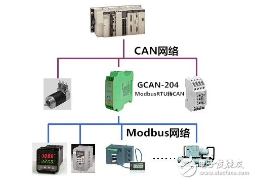
Modbus was invented in 1979 by Modicon (now a brand of Schneider Electric) and is the world's first bus protocol for industrial sites. The ModBus network is an industrial communication system that is connected by a programmable controller with a smart terminal and a computer via a public line or a local dedicated line. Its system structure includes both hardware and software. It can be applied to a variety of data acquisition and process monitoring. The ModBus network has only one host and all communications are sent by him. The network can support as many as 247 remote slave controllers, but the actual number of slaves supported is determined by the communication device used. With this system, each PC can exchange information with the central host without affecting each PC's own control tasks.
Modbus rtu communication protocolWhen a communication command is sent to the instrument, the device conforming to the corresponding address code receives the communication command, removes the address code, reads the information, and if there is no error, performs the corresponding task; and then returns the execution result to the sender. The returned information includes the address code, the function code for performing the action, the data of the result after the action is performed, and the error check code. If there is an error, no information will be sent.
1. Information frame structureAddress code function code data area error check code
8-bit N &TImes; 8-bit 16-bit
Address code: The address code is the first byte (8 bits) of the information frame, from 0 to 255. This byte indicates that the slave set by the user will receive the information sent by the host. Each slave must have a unique address code, and only the slaves that match the address code can respond to the loopback. When the slave sends back information, the equivalent address code indicates where the information came from.
Function code: The function code sent by the host tells the slave what task to perform. The function codes listed in Table 1-1 have specific meanings and operations.
Data area: The data area contains the return information that needs to be performed by the slave or collected by the slave. This information can be a numeric value, a reference address, and the like. For example, if the function code tells the slave to read the value of the register, the data area must contain the start address and read length of the register to be read. For different slaves, the address and data information are different.
Error check code: The host or slave can use the check code to determine whether the received message is in error. Sometimes, due to electronic noise or some other interference, the information will change slightly during the transmission process. The error check code ensures that the master or slave does not work for the information that is wrong during the transmission. This increases the security and efficiency of the system. The error check uses the CRC-16 check method.
Note: The format of the information frame is basically the same: address code, function code, data area and error check code.
2. Error checkThe redundant cyclic code (CRC) consists of 2 bytes, which is a 16-bit binary. The CRC code is calculated by the transmitting device and placed at the end of the transmitted message. The device receiving the information recalculates the CRC code of the received information, and compares whether the calculated CRC code matches the received one. If the two do not match, it indicates an error.
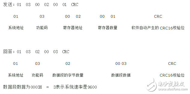
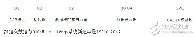
First, set the communication speed of the system: address 01, set 0x0002 address register to read and write registers can set the corresponding rate 01 = 2400, N, 8, 1 02 = 4800, N, 8, 1 03 = 9600, N,8,1 ,04=19200,8,N,1
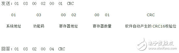
1, read the internal register (communication rate) command
2. Modify the internal register (communication rate) command [Change 9600 (code 03) to 19200 (code 04)]
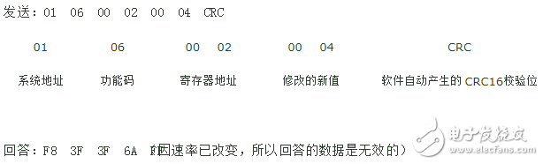
Verify successful (change the serial port baud rate of the host to 19200)
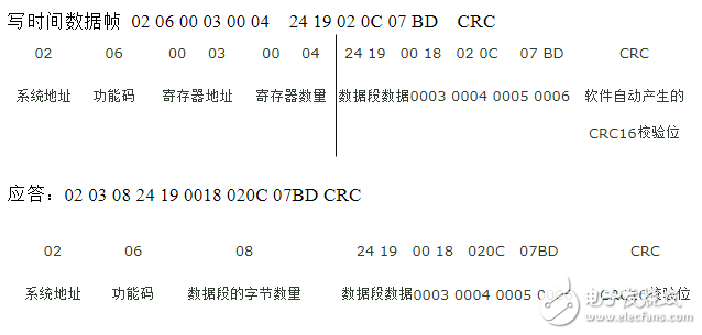
Second, the school time data frame format (address 02, set 0x0003 0004 0005 0006 register placement time parameters from low to high, format: 2011:02:12 18:36:25)
Write the decimal 2011:02:12 18:36:25 (07DB:020C 0018 2419) to the register:
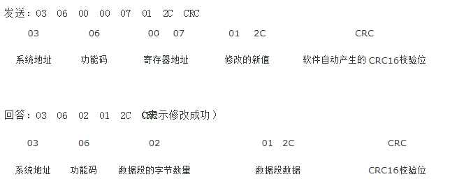
Third, sampling frequency data frame format (address is 03, 0x0007 register placement sampling frequency parameter 0-300, (0000-012C))
Fourth, start the sampling point to set the data frame format requirements (address is 04, register is 0x0008, the frequency setting range is 0032-2710, 50Hz-10000Hz)
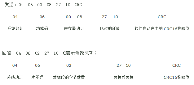
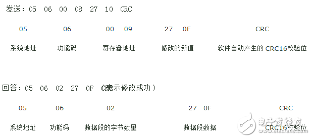
Five, data calculation RF set frame requirements (address 05, register is 0x0009, parameter range 0001-9999 (0001-270F))
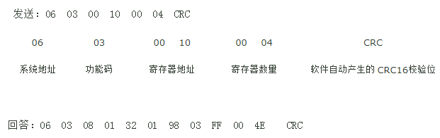
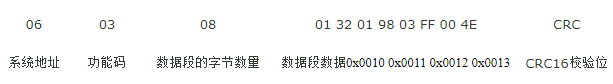
Six, read the 4-way bridge sensor data data frame requirements: (address is 06, register address 0x0010 0x0011
0x0012 0x0013)
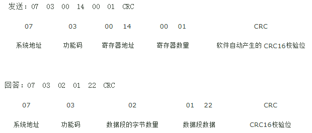
Seven, read the temperature data frame requirements: address 07, register 0x0014,
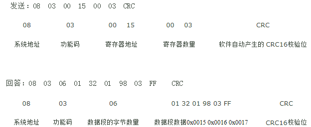
Eight, read 3 acceleration data frame requirements: address 08, register address 0x0015 0x0016 0x0017
Electronic Cigarette,Largest E-Cig Oem,China E-Cig Oem,Vape Pen Oem,Vape Device Oem
Shenzhen MASON VAP Technology Co., Ltd. , https://www.e-cigarettefactory.com