Teach you to make the seal design of the measuring chamber of the rotary piston flowmeter
Rotating piston flow metering chamber structure and working principle
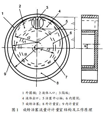
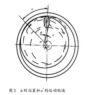
As shown in Fig. 1, the piston 7 which can accommodate the positional gap of the partition when the top surface is open is located in the annular wall formed by the inner wall of the outer cylinder 1 and the outer wall of the inner cylinder 6, and the inner and outer walls of the piston are respectively combined with the inner and outer cylinders. The outer and inner wall contacts make the center o' of the piston have an offset e from the center o of the inner and outer cylinders. It is easy to see that the outer inner radius r 1, r 2 of the rotary piston and the inner and outer radius R, r 3 of the outer inner cylinder Have the following relationship:
Piston wall thickness δ= r 1- r 2 Offset e= R - r 1 Piston outer radius r 1= ( R + r 3+ δ) / 2 The inner and outer cylinders are partitioned between the inner and outer cylinders along the radial partition.
The radial dimension of the annular zone I = R - r 3 The length of the partition in R is slightly larger than l The thickness of the partition is b. The distance from the partition to the o point l 2 = R - l 1
In this way, the annular zone is divided into two crescent-shaped inner and outer chamber measuring chambers by the piston wall and the partition plate. Under the action of the inlet liquid pressure, the piston center o' rotates counterclockwise along the arrow, and the rest of the piston moves in the annular region. The inner and outer cylindrical surfaces are in contact with the inner and outer cylinders in sequence, and the metering chamber continuously moves circumferentially to transport fluid. The center of the piston o' rotates around o for one week, and the inner and outer metering chambers rotate at the same time for one week, and each liquid discharges a liquid. The volume of the inside and outside of the crescent-shaped metering chamber is the volumetric flow rate of the liquid discharged during the rotation of the center of the piston. It is a measurable constant:

Where h - the height of the measuring chamber
The amount of liquid flowing at n revolutions can be measured based on the number of revolutions n of the piston:

Analysis of sealing problems in flow metering chamber
1, the principle of sealing
According to the above analysis of the structure and working principle of the flowmeter, when the piston is working, the outer circular surface of the piston and the inner circular surface of the outer cylinder are in contact with each other, and the upper and lower surfaces of the partition plate and the cylinder constitute an external measuring chamber; The outer cylindrical outer surfaces of the inner cylinder are in contact with each other, and the upper and lower surfaces of the partition plate and the cylinder constitute an inner measuring chamber. When the piston moves, it is required to have a gap between the top surface and the partition plate to ensure that the movement is not interfered. More importantly, the notch profile must also ensure that it is always in contact with the near center k of the partition to ensure internal measurement. The seal of the chamber; otherwise, the liquid input from the inlet with pressure will not pass through the metering chamber, but directly flow out through the gap into the outlet, which may result in inaccurate metering, and the flow meter will not work.
2. Analysis and design calculation of the notch profile equation of the top surface of the piston
1) As shown in Figure 2, when the rotary piston is working, its center o' rotates counterclockwise, and the angle between the line connecting the oo' and the initial position is α, and α is used as the parameter to derive the polar coordinate parameter equation of the top notch profile. . For the convenience of design and processing, the polar coordinate system is fixed on the top surface of the piston. Let the origin of the coordinate system be o', the initial position of the polar axis is the symmetry line o'B of the notch profile, and the clockwise direction is the phase angle positive φ.
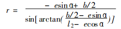
When 0° ≤ α ≤ 180°, the right half-profile equation of the notch is derived as:
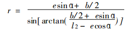

Wherein e, b, l 2, and r 1 are all as described above.
2) When 180 ° ≤ α ≤ 360 ° due to the symmetry relationship, - α, - φ instead of α, φ in (1) can obtain the polar coordinate equation when 180 ° ≤ α ≤ 360 °:

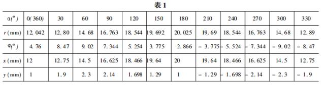
3. Calculate the raw data by example : R = 27 mm, r 1 = 23 mm, r 2 = 21 mm, r 3 = 17 mm, l 1 = 11 mm, b = 2 mm
After calculating e = R - r 1 = 4 mm, l 3 = 16 mm, the corresponding values ​​of the parameter α from small to large to r and φ are shown in Table 1.
Profile processing
Convert (1) and (2) to a Cartesian coordinate equation, as shown in Figure 3:

(3) The equation is still the parametric equation of α. It is difficult to directly obtain the functional relationship y = f ( x ) of y and x. The corresponding value of x, y can be obtained according to the given alpha value (see the table above). The corresponding coordinate points are used as nodes, and the equation of y = f ( x ) of the segment is established by Newtonian differential interpolation or spline interpolation; based on the equation, a program can be programmed to conveniently perform processing on the NCN wire cutter.
Other measures to improve seal reliability
1) The leakage of liquid at the top surface of the piston mainly occurs in the inner measuring chamber, and the communication time between the inner measuring chamber and the inlet is shortened as much as possible to reduce the time course of pressure. When designing the shape and position of the inlet, the inlet is as close as possible. The inner cylindrical surface of the cylinder.
2) Similarly, the shape of the liquid outlet should be placed in the same position as the metering chamber as soon as possible.
Conclusion
1. In addition to the dimensional relationship between the radius of the cylinder and the eccentricity of the piston radius, the dynamic seal of the measuring chamber of the rotary piston flowmeter should make the inner and outer cylinders of the piston tangent to the cylindrical surface of the inner and outer cylinders. Consider the design of the contact seal of the top surface of the piston and the gap of the partition, that is, the notch.
2. The notch profile design of the top surface of the piston should not only interfere with its normal motion, but also consider the dynamic sealing problem. Therefore, the shape of the notch is not arbitrary, but is carefully designed as shown in Figure 3.
3. The notch profile of the top surface of the piston can be calculated according to the formulas (1) and (2).
4. The profile can obtain the node fitting interpolation equation through the (1), (2), and (3) parametric equations, and complete the machining on the CNC wire cutting machine.
5. This flowmeter is a portable device produced by Shanghai Kanghui for the fuel flow detection and verification.
Ningbo Autrends International Trade Co.,Ltd. , https://www.ecigarettevapepods.com