What should be noted when installing and wiring the PLC?
Although plc is a control device that is specially used in the field, many measures have been taken during design and manufacture to make it more adaptable to the industrial environment. However, in order to ensure the stability and reliability of the entire system, PLC should still have good working environment conditions as far as possible. Take the necessary anti-jamming measures.
1
PLC installation
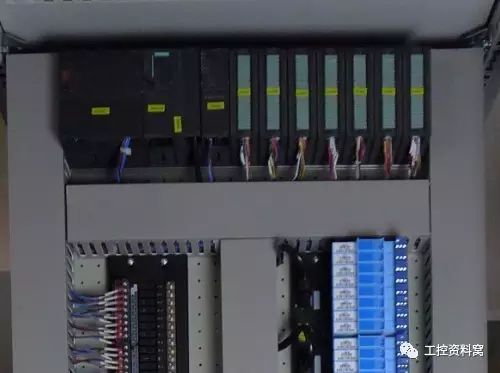
PLC is suitable for most industrial scenes, but it still has certain requirements for the use occasion, ambient temperature and so on. Controlling the working environment of the PLC can effectively increase its working efficiency and life. When installing the PLC, avoid the following places:
(1) The ambient temperature exceeds the range of 0 ~ 50 °C;
(2) The relative humidity exceeds 85% or there is dew condensation (caused by sudden temperature changes or other factors);
(3) direct sunlight;
(4) Corrosive and flammable gases such as hydrogen chloride, hydrogen sulfide, etc.;
(5) There are iron filings and dust;
(6) Frequent or continuous vibrations with vibration frequencies of 10 to 55 Hz and amplitudes of 0.5 mm (peak to peak);
(7) Impact exceeding 10 g (gravitational acceleration). All four corners of the small programmable controller cover have mounting holes. There are two ways to install, one is to fix with screws, different units have different mounting dimensions; the other is DIN (German Republican standard) fixed track. The mounting plate used for the DIN rail is a pair of left and right. On the rail, first install the left and right clamps, install the PLC, and then tighten the screws. In order to make the control system work*, the programmable controller is usually installed in a control cabinet with a protective cover to prevent dust, oil, water from splashing. In order to ensure that the programmable controller maintains its temperature within the specified ambient temperature range during operation, the installation machine should have sufficient ventilation space, and there must be a gap of more than 30mm between the basic unit and the expansion unit. If the ambient temperature exceeds 55C, install an electric fan and force ventilation.
In order to avoid electrical interference from other peripheral devices, the programmable controller should be as far away as possible from the high-voltage power lines and high-voltage devices, and a distance of at least 200 mm should be allowed between the programmable controller and the high-voltage devices and power lines. When the programmable controller is installed vertically, it is necessary to prevent wire ends, iron filings, etc. from falling into the programmable controller from the ventilation window, causing a short circuit in the printed circuit board, making it unable to work normally or even permanently damaged.
2
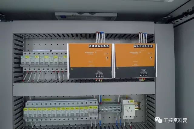
Power connection PLC power supply is 50Hz, 220V±10% AC. FX series programmable controllers have DC 24V output terminals. This terminal provides DC 24V power for input sensing (such as photoelectric switch or proximity switch). If the power supply fails and the interruption time is less than 10ms, the PLC operation will not be affected. If the power interruption exceeds 10ms or the power supply drops below the permissible value, the PLC stops operating and all output points are disconnected at the same time. When the power is restored, if the RUN input is turned on, the operation is automatically performed. For interference from the power line, the PLC itself has sufficient resistance. If the power supply interference is particularly severe, an isolation transformer with a 1:1 ratio can be installed to reduce the interference between the equipment and ground.
3
A well-grounded grounding is an important condition for ensuring the reliable operation of the PLC and can avoid accidental voltage surge hazards. The grounding wire is connected to the ground of the machine and the basic unit is grounded. If an extension unit is to be used, its grounding point should be connected to the grounding point of the base unit. In order to suppress the interference added to the power supply and the input and output terminals, the programmable controller should be connected to a special ground wire. The grounding point should be separated from the grounding point of the power equipment (such as the motor). If this requirement is not met, it must be connected to a common ground with other equipment and must not be connected in series with other equipment. The grounding point should be as close to the PLC as possible.
4
DC 24V terminal
When using a passive contact input device, the PLC's internal 24V supply supplies 7mA per point to the input through the input device. The 24V terminal on the PLC can also supply current to an external sensor such as a proximity or photoelectric switch. When the 24V terminal is used as a sensor power supply, the COM terminal is a DC 24V ground terminal. If extended crew is used, the 24V end of the base unit and extension unit should be connected. In addition, any external power supply cannot be connected to this terminal. If an overload occurs, the voltage will drop automatically and this point input has no effect on the programmable controller. The number of input points for each type of PLC is specified. For each unused input point, it does not consume power, so in this case, the ability of the 24V power supply terminal to supply current to the outside can increase. The vacancy terminal of the FX series PLC cannot be used under any circumstances.
5
The input connection PLC generally accepts input switch signals such as limit switch and limit switch. The input terminal is the port for PLC and external sensor load conversion signal. Input wiring generally refers to the wiring of external sensors and input ports. The input device can be any passive contact or open collector NPN tube. When the input device is turned on, the input is turned on and the input line is closed while the LED of the input indicator lights up. Between the primary circuit and the secondary circuit at the input end, optocoupler isolation is used. The secondary circuit has an RC filter to prevent malfunction of the PLC due to chattering of the input contacts or electrical noise from the input lines. If a diode is connected in series with the input contact circuit, the voltage across the series diode should be less than 4V. If you use a reed switch with a light emitting diode, the number of series diodes cannot exceed two. In addition, input wiring should also pay special attention to the following points:
(1) The input wiring should not exceed 30m. However, if the ambient interference is small and the voltage drop is not large, the input wiring can be longer.
(2) The input and output lines cannot use the same cable, and the input and output lines should be separated.
(3) The width of the pulse signal that the programmable controller can accept should be greater than the scan cycle time.
6
Output wiring
(1) The programmable controller has three forms of relay output, thyristor output, and transistor output.
(2) Output wiring is divided into independent output and common output. When the output relay or thyristor of the PLC is activated, the two outputs of the same number are switched on. In different groups, different types and voltage levels of output voltage can be used. However, the output in the same group can only use the same type of power supply with the same voltage level.
(3) Since the output element of the PLC is packaged on the printed circuit board and connected to the terminal board, if the load connected to the output element is short-circuited, the printed circuit board will be burned. Therefore, the fuse protection output element is applied.
(4) When relay output is used, the amount of inductive load that is subjected to affects the working life of the relay, so the relay has a long service life.
(5) The output load of the PLC may cause noise interference, so take measures to control it. In addition, for dangerous loads that can cause damage to the user, in addition to being considered in the control program, an external emergency stop circuit should also be designed so that when the programmable controller fails, the load-causing power source can be cut off. Do not use the same cable for the AC output line and the DC output line. The output line should be as far away from the high voltage line and the power line as possible to avoid parallelism.
Butt Connector,Lugs Insulated Female Connectors,Insulated Female Connectors,Non-Insulated Spade Terminals Wire Connector
Taixing Longyi Terminals Co.,Ltd. , https://www.longyicopperterminals.com