Analysis of Eleven Classical Opamp Circuits
The circuit composed of operational amplifiers is varied and dazzling. It is the focus of learning in analog circuits. If you do not grasp the core when analyzing its working principles, it is often tempting. For this reason, I specially searched the application of the world's operational amplifier circuit and came to have a “Budding Solutionâ€. I hope that you will gain something after watching it.
Throughout the books and courses of all analog electronic technologies, when introducing an operational amplifier circuit, it is nothing more than a first step to characterize the circuit. For example, this is a non-inverting amplifier, and then it derives the relationship between its output and its input, and then Vo=(1+Rf)Vi, that is an inverting amplifier, and then we get Vo=-Rf*Vi... At the end of the year, students often come up with the impression that you can remember the formula! If we change the circuit a bit, they won't find it!
Today, teach you invincible two strokes, these two strokes are clearly written in all the teaching materials of the op amp circuit, that is, "virtual shortness" and "virtual power", but if you want to use it to make things better, you must have a comparison. Deep foundation. Short and imaginary concept
Due to the large voltage amplification of the op amp, the open-loop voltage amplification of the general-purpose op amp is more than 80 dB. The output voltage of the op amp is limited, typically between 10 V and 14 V. Therefore, the differential amplifier input voltage of the operational amplifier is less than 1 mV, and the two input terminals are approximately equal potential, which is equivalent to a "short circuit." The larger the open-loop voltage amplification, the closer the potentials of the two input terminals are.
"Virtual short" means that when the analysis operational amplifier is in a linear state, the two input terminals can be regarded as equipotential. This characteristic is called false short circuit, short for short. Obviously it is not possible to really short the two inputs.
Due to the large differential input resistance of the op amp, the input resistance of a general-purpose op amp is above 1 MΩ. Therefore, the current flowing into the input terminal of the op amp is often less than 1uA, which is much less than the current of the external circuit of the input terminal. Therefore, the two input terminals of the op amp are usually regarded as open circuits, and the greater the input resistance is, the closer the two input terminals are to the open circuit. "Virtually broken" means that the two input terminals can be regarded as equivalent open circuits when analyzing the operational amplifier in a linear state. This feature is called false open circuit, or short circuit. Obviously the two inputs cannot be truly open circuited.
When analyzing the operational principle of the op amp circuit, first of all, please forget about what the same direction amplification, inverse amplification, what adder, subtracter, what differential input ... temporarily forget the formula of the input and output relations ... These only It will interfere with you and make you more confused. Also, please ignore the input circuit parameters such as bias current, common-mode rejection ratio and offset voltage temporarily. This is a matter for designers to consider. We understand that the ideal amplifier (in fact, in the maintenance and most of the design process, the actual amplifier as an ideal amplifier for analysis will not be a problem).
Well, let us grasp two "planar ax" - "virtual short" and "virtual broken", and began to "get rid of cattle".
1) Inverting Amplifier:
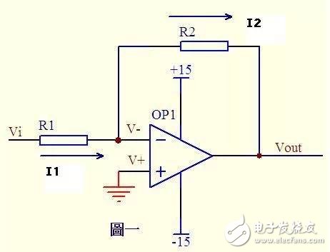
figure 1
Figure 1 op amp's co-terminal ground = 0V, reverse terminal and co-terminal terminal short, so it is 0V, reverse input input resistance is high, virtual broken, almost no current injection and outflow, then R1 and R2 quite Thus, the current flowing in series through each component in a series circuit is the same, that is, the current flowing through R1 is the same as the current flowing through R2.
Current flowing through R1: I1 = (Vi - V-)/R1 .........a
Current flowing through R2: I2 = (V- - Vout)/R2 ...b
V- = V+ = 0 ..................c
I1 = I2 ........................d
Solve the above junior high algebraic equation by Vout = (-R2/R1)*Vi
This is the input and output relationship of the legendary inverting amplifier.
2) Same direction amplifier:
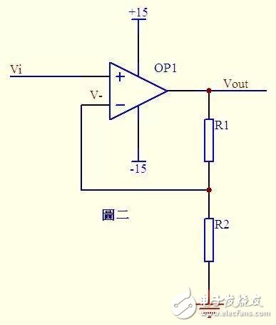
figure 2
In Figure 2, Vi and V- are short, then Vi = V-...a
Because of the virtual disconnect, there is no current input and output at the inverting input. The current through R1 and R2 is equal. Let this current be I, which is obtained by Ohm's law: I = Vout/(R1+R2) ...b
Vi is equal to the partial pressure on R2, ie: Vi = I*R2 ...c
By the abc formula Vout = Vi * (R1 + R2) / R2 This is the legend of the same direction amplifier formula.
3) Adder 1:
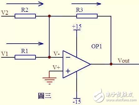
image 3
In Figure 3, from the virtual short: V- = V+ = 0 ... a
According to the virtual break and Kirchhoff's law, the sum of the currents passing through R2 and R1 is equal to the current through R3, so (V1 - V-)/R1 + (V2 - V-)/R2 = (V - - Vout) /R3 ...b
Substitute into a, b-type into V1/R1 + V2/R2 = Vout / R3 If you take R1 = R2 = R3, then the formula into -Vout = V1 + V2, this is the legendary adder.
4) Adder 2:
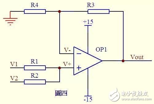
Figure 4
Please see Figure 4. Because of the virtual disconnection, no current flows through the same side of the op amp, the current flowing through R1 and R2 is equal, and the current flowing through R4 and R3 is also equal.
Therefore (V1 - V+)/R1 = (V+ - V2)/R2 ...a
(Vout - V-)/R3 = V-/R4 ...b
From the imaginary short knowledge: V+ = V- ......c If R1 = R2, R3 = R4, from the above formula can be derived V + = (V1 + V2) / 2 V- = Vout / 2 so Vout = V1 + V2 Is also an adder, Oh!
5) Subtractor
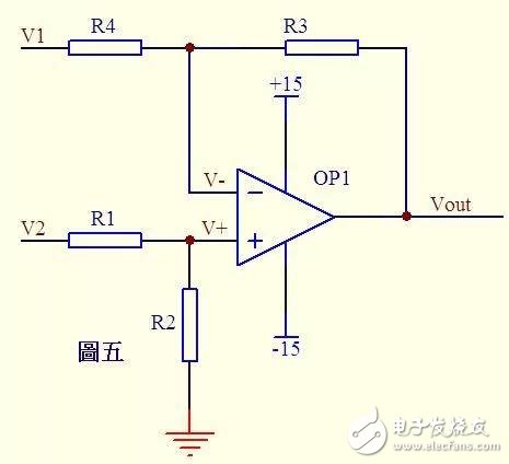
Figure 5
In Fig. 5, it is known by virtual assumption that the current through R1 is equal to the current through R2, and the current through R4 is equal to the current through R3, so (V2 - V+)/R1 = V+/R2...a
(V1 – V-)/R4 = (V- - Vout)/R3 ...b
If R1=R2, then V+ = V2/2...c
If R3 = R4, then V- = (Vout + V1)/2 ... d
From the virtual short knowledge V+ = V- ... e
So Vout=V2-V1 This is the legendary subtractor.
6) Integral circuit:
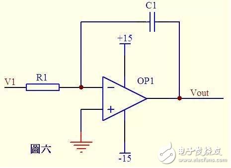
Figure 6
In the circuit of Figure 6, from the virtual short, the voltage at the inverting input is equal to that at the same direction.
By false assumptions, the current through R1 is equal to the current through C1.
Current through R1 i = V1/R1
Current through C1 i=CdUc/dt=-CdVout/dt
So Vout = ((-1/(R1*C1))∫V1dt The output voltage is proportional to the integral of the input voltage over time. This is the legendary integration circuit.
If V1 is a constant voltage U, the equation above is converted to Vout = -Ut/(R1C1) When t is time, the Vout output voltage is a straight line that changes from 0 to the negative supply voltage in time.
7) Differentiation circuit:
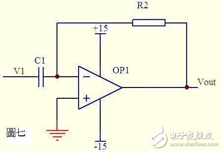
Figure 7
In Fig.7, it is known from the imaginary fault that the current through the capacitor C1 and the resistor R2 is equal. From the imaginary short knowledge, the voltages at the same and opposite ends of the operational amplifier are equal.
Then: Vout = -i * R2 = -(R2*C1)dV1/dt
This is a differential circuit.
If V1 is an abruptly added DC voltage, the output Vout corresponds to a pulse in the opposite direction to V1.
8) Differential Amplifier Circuit
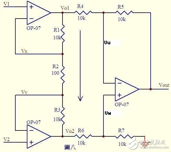
Figure 8
From the virtual short knowledge Vx = V1 ...a
Vy = V2 ...b
According to imaginary knowledge, no current flows through the input of the op amp. R1, R2, and R3 can be considered as series. The current through each resistor is the same. Current I=(Vx-Vy)/R2...c
Then: Vo1-Vo2=I*(R1+R2+R3) = (Vx-Vy)(R1+R2+R3)/R2...d
According to imaginary knowledge, the current flowing through R6 is equal to the current flowing through R7. If R6=R7, then Vw = Vo2/2...e
Similarly, if R4 = R5, Vout - Vu = Vu - Vo1, so Vu = (Vout + Vo1)/2 ... f
From the virtual short, Vu = Vw ... g
Vout = Vo2 - Vo1 ......h from efg
Vout = (Vy - Vx) from dh (R1 + R2 + R3)/R2 where (R1 + R2 + R3)/R2 is a fixed value, which determines the magnification of the difference (Vy - Vx).
This circuit is the legendary differential amplifier circuit.
9) Current detection:
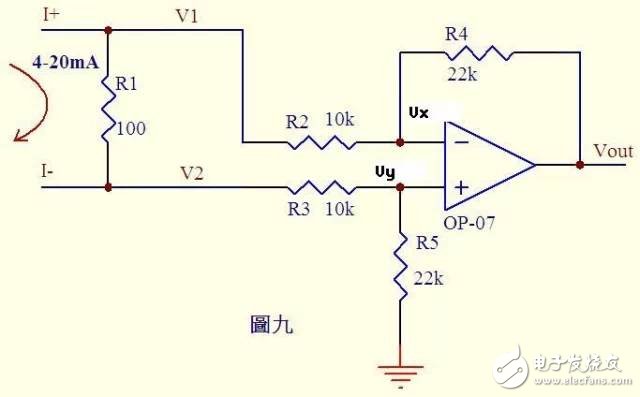
Figure 9
Analyze a circuit that everyone touches more. Many controllers accept 0~20mA or 4~20mA current from various detection instruments. The circuit converts this current into voltage and then sends the ADC to convert it into a digital signal. Figure 9 shows this typical circuit. As shown in Figure 4~20mA current flowing through the sampling 100Ω resistor R1, a voltage difference of 0.4~2V will be generated on R1. From the imaginary knowledge that there is no current flowing through the input of the operational amplifier, the current flowing through R3 and R5 is equal, and the current flowing through R2 and R4 is equal. Therefore:
(V2-Vy)/R3 = Vy/R5 ...a
(V1-Vx)/R2 = (Vx-Vout)/R4 ...b
From the virtual short: Vx = Vy ......c
Current changes from 0~20mA, then V1 = V2 + (0.4~2) ...d
Substituting cd equation into b formula (V2 + (0.4~2)-Vy)/R2 = (Vy-Vout)/R4...e
If R3=R2 and R4=R5, Vout=-(0.4~2)R4/R2...f from ea
In Fig. 9 where R4/R2 = 22k/10k = 2.2, f-type Vout = -(0.88-4.4)V,
That is to say, the 4~20mA current is converted into a voltage of -0.88 ~ -4.4V, and this voltage can be sent to the ADC for processing.
Note: If we reverse the current in Figure 9, Vout = +(0.88~4.4)V
10) Voltage and current conversion detection:
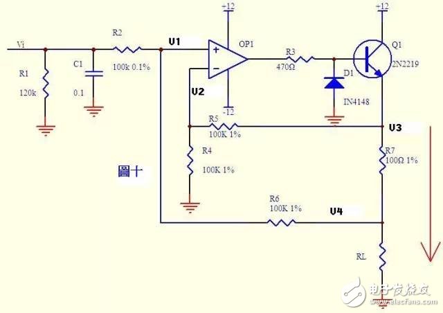
Figure 10
Current can be converted into voltage, and voltage can also be converted into current. Figure 10 is such a circuit. The negative feedback in the figure above is not directly fed back through the resistor. Instead, the emitter junction of the transistor Q1 is connected in series. Do not think that it is a comparator. As long as it is an amplifying circuit, the rule of virtual short-break is still consistent!
By the virtual default, no current flows through the input of the op amp.
Then (Vi – V1)/R2 = (V1 – V4)/R6 ...a
Similarly (V3 – V2)/R5 = V2/R4 ...b
From the virtual short knowledge V1 = V2 ... c
If R2 = R6, R4 = R5, from the abc formula V3-V4 = Vi
The formula above shows that the voltage across R7 is equal to the input voltage Vi, then the current through R7 is I=Vi/R7. If the load is RL<<100KΩ, the current through R1 and through R7 is basically the same.
11) Sensor detection:
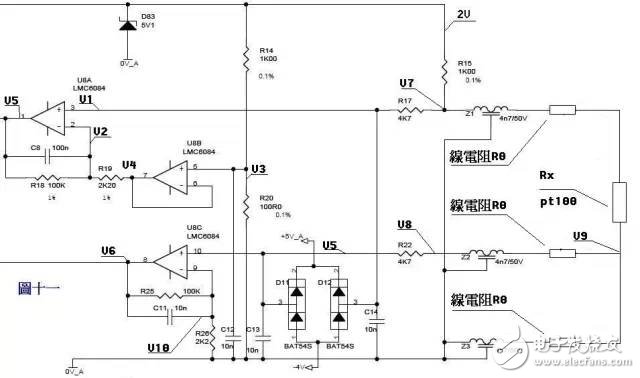
Figure 11
To a complicated, Oh! Figure 11 shows a three-wire PT100 preamplifier circuit. The PT100 sensor leads to three wires of the same material, wire diameter and length. The connection method is as shown in the figure. A voltage of 2V is applied to the bridge circuit composed of R14, R20, R15, Z1, and PT100 and their line resistance. Z1, Z2, Z3, D11, D12, D83 and each capacitor play a role of filtering and protection in the circuit. They can be ignored during static analysis. Z1, Z2, and Z3 can be regarded as short circuits, and D11, D12, and D83 as well as capacitors can be seen. To open the way. Known by the resistance voltage division, V3=2*R20/(R14+20)=200/1100=2/11...a
From the virtual short, U8B pin 6,7 pin voltage and pin 5 voltage equal V4=V3 ...b
From the virtual knowledge that no current flows through pin 2 of U8A, the current flowing through R18 and R19 is equal. (V2-V4)/R19=(V5-V2)/R18 ......c
From the virtual fault knowledge, there is no current flowing through pin 3 of U8A. V1 = V7 ... d In the bridge circuit, R15 is connected in series with Z1, PT100 and the line resistance. The voltage divided in series with PT100 and line resistance is added to U8A through resistor R17. Pin 3, V7=2*(Rx+2R0)/(R15+Rx+2R0) .....e
From the virtual short, U8A pin 3 and pin 2 are equal in voltage, V1 = V2 ... f
From abcdef, (V5-V7)/100=(V7-V3)/2.2 Simplify V5=(102.2*V7-100V3)/2.2 ie V5=204.4(Rx+2R0)/(1000+Rx+2R0) – 200/11 ......g
The above output voltage V5 is a function of Rx. Let's look at the effect of line resistance. The voltage drop across the lowermost line resistance of Pt100 passes through the middle line resistance, Z2, and R22, and is added to pin 10 of U8C.
From the virtual default, V5=V8=V9=2*R0/(R15+Rx+2R0)...a
(V6-V10)/R25=V10/R26 ...b
From the virtual short, V10=V5...c
From formula abc V6=(102.2/2.2)V5=204.4R0/[2.2(1000+Rx+2R0)]......h Known from the equations made up by formula gh, if the values ​​of V5 and V6 are measured, they can be calculated. Rx and R0, know Rx, check pt100 index table to know the size of the temperature.
R&M PARADISE is 10000 puffs Disposable Vape Ecig with type-c port rechargeable model
Newest technology in Disposable Electronic Cigarettes mesh coil with SUB-OHM 0.5Ω and 9pcs inlet oil holes design, let the atomization to the extreme by lung suction, cloud Beast, enjoy amazing massice clouds and good tastes.This Disposable Vape Prefilled E-liquid visual tank with RGB flash light implanted, no filling, no pulling plug, no switching, simple and fun to vape directly.
R&M LEGEND 10000 Puff is Adjustable rotatable airflow control, DIY vape volume liek R&M BAR 9000 Puff.
New generation vape R&M PARADISE, bring you the enjoyment and pleasure of paradise.
Find more RM product here like R&M LEGEND 10000 Puff and R&M 1000 Puffs/R&M Monster 7000 puff.
Mesh coil Disposable Vape Ecig TUG BOAT EVO and Tugboat Mega 4000 Puffs.
Pod Vape,Vape Pod ,Disposable Pod
Shenzhen Essenvape Technology Co., Ltd. , https://www.essenvape.com