Share some development experience of single chip microcomputer
The old-fashioned topic has come again. I feel that I have seen a lot of experience in the development of single-chip microcomputers, but not necessarily those that are suitable for you. "The book is read a hundred times and it’s righteous." On the way to pursue learning, we never end. .
Probe into the development of single chip microcomputer
Doing AT89C5X (51, 52, 55, etc.) takes the longest time, and may know more. It mainly talks about the experience and lessons in practical applications. The book can refer to a special edition of the AT89 series from Beihang. It is not bad. I suggest you buy it.
AT89C51 I think it is a very standard 51 single-chip microcomputer, 4 P port, 1 serial port, RAM only standard 128Byte, Flash is only 4K, the function is still complete, I will use it as the basis, so encountered during the development process The problem.
Reset source problem
The most common reset method for everyone is the resistor plus capacitor. The AT89C51 is a high-level reset. This method is unstable and can be used during product debugging. Because we usually use the emulator during debugging, many emulators will output their own. Reset signal, and shield the reset signal generated by the target board, so the reset signal is no problem during debugging. Our company uses Changsha Juyang's emulator, which uses advanced technology, and can be used to simulate AT89 series. The chip has no problem at all, and it is still very stable.
Here is a very important question to say, sometimes you will encounter such a problem: your own program does not have a problem running during the simulation, but it does not work after burning. There are two reasons for combining my experience. First, the timing may change. Everyone knows that I don't say much. Another reason is the problem of resetting the signal. Details are as follows:
(1) There is a problem with the reset circuit, and the reset signal cannot be generated normally. Because the emulator may provide you with a reset signal during debugging, it will not be available after leaving the emulator;
(2) The problem of the watchdog. Some 51 chips have a watchdog reset function, such as At89c55WD. When the program turns on the watchdog, sometimes the initialization content of the program is too much, and a reset signal is often generated, especially when using the C language programming function. Although you obviously close the watchdog somewhere at the beginning of the program, the program will still reset, because the C language execution efficiency is lower than the assembly, it looks like a few lines of code, sometimes it takes a long time, so in Be sure to pay attention to this problem when using a dog.
This problem is easily overlooked when using the emulator, because even if the watchdog is reset in your program, the emulator (the Juyang emulator can turn on/mask this function) will often block the reset signal, so the program still Will work fine.
When you run the program and then run it, you can't run it properly until you find the program you just debugged. That's because your program has been resetting all the time. Note that you can't see the reset by using the oscilloscope to observe the RST pin. Signal because the watchdog reset does not affect the level of the RST pin.
In another case, there is no watchdog inside the chip, but there is a CPU monitor chip in the circuit. It is often able to provide a reset signal, and it is a reset signal for various reasons. If you find the above, you can use an oscilloscope. Check the RST pin to see if there is a level change.
Therefore, it is recommended that you use the CPU monitor chip when you are doing 51 product development. It is very easy to use the X5045, because it also has the Eprom function. This can be used in many occasions, and you can also use the dedicated reset chip such as MAX708. Stable and convenient.
Summary of notes
The following are some of the notes taken in conjunction with your own actual work:
1. Calculation and selection of the resistance (exclusion resistance) in series with the LED. Generally, the normal luminous current of the LED is 3~10mA, and the voltage drop generated on the LED is 1.7V (rail tube) R=(5- 1.7)/3~10 (k)
2. The TTL level of the single chip is high: +5V; low level: 0V.
RS232 serial port level high level: -12V; low level: +12V. The level can be converted between the MAX232 level conversion chip.
3. The register of the I/O port of the single-chip power-on is high level, and the other registers are low level.
4. Switching effect of triode: Indirect forward voltage in B and E, E and C are conducting.
5, buzzer:
1) The active buzzer can be continuously sounded by directly connecting to the rated voltage.
2) The passive buzzer is the same as the electromagnetic speaker and needs to be connected to the audio output circuit to sound.
3) Active buzzer with oscillation source, passive without.
4) The ideal signal for the active buzzer is direct current.
5) The ideal signal of the passive buzzer is a square wave signal.
Square wave sound function: void beep()
{ fmq=0;
Delay 500us();
Fmq=1;
Delay 500us();
}
6, calculate the microcontroller instruction cycle:
Instruction cycle (us) = 12 / crystal frequency (Mhz)
Choose 12M crystal oscillator, one instruction cycle is 1us
7, 89C51 chip supports up to 24M crystal
Throwing bricks to attract jade - learning from the older generation
The above is just a rough little insight of the author. The author and everyone will feel that it is not very enjoyable. The stone of the mountain can be used to attack jade. We still need to learn from more predecessors. After reviewing the experience of the predecessors, the author has seen a lot worthwhile. Some development experiences shared by everyone!
At present, there are many articles about MCU application, but there are few articles about MCU development tools. Since the MCU is a very practical course, if the traditional development mode is adopted, it is necessary to purchase an expensive simulator, a programmer and other development tools for experimentation.
In fact, due to the increasingly perfect chip function, we can use the system's system programming (ISP) function to produce practical and low-cost development tools. Let's help DIY enthusiasts develop and develop their own development tools.
1 current common development mode
Currently, there are basically two development modes to choose from: using an emulator and using a programmer.
1 Use the emulator. Advantages: Convenient, you can set breakpoints, you can observe the contents of the memory and registers. Disadvantages: expensive, different types of microcontrollers to buy different emulators; emulators are not microcontrollers, sometimes the code can pass on the emulator, but in the microcontroller can not work properly, but increased the difficulty of debugging.
2 Use the programmer. Advantages: The price is relatively cheap, usually a programmer can program a variety of devices. Disadvantages: The operation is quite inconvenient, each time the chip is transferred between the target board and the programmer, and also between the compile operation interface and the programmer operation interface, most of the time is doing simple repetitive work.
2 new development mode introduction and chip selection
The development tools described in this article use a new development model (similar to the programmer development model). Since the in-system programming function of the chip is utilized, there is no need to move the chip. Designed in software design: Once the code file is re-edited, it is automatically downloaded to the chip and automatically reset to run, which is the real "coded".
At present, many microcontrollers support system programming. The 8051 series MCU supports a lot of system programming, but most of them support programming the MCU through the serial port of the PC.
There are four inconvenient places: one is that the project itself is inconvenient to communicate with the PC serially; the other is to add a MAX232 level-shifting chip; the third is that some chips must enter the download mode according to specific steps, the programming process Manual intervention is required. Fourth, some chips require firmware (customized program) support. If the firmware is accidentally damaged, the system's system programming function is gone.
After comparison, Atmel's AT89S8252 is an ideal chip for production tools. This chip has the following characteristics:
â—† Compatible with 8051;
â—† Contains 8KB of program memory that can be erased 1000 times, 2KB can erase more than 100,000 data memory and 256 bytes of 8-bit wide internal RAM;
â—† Can be serially programmed in the system via SPI interface, compatible with 8051
â—† There is an automatic erasing cycle during serial programming, which can be downloaded in sections when debugging large programs, saving time;
â—† Low voltage download, no need for 12V programming voltage.
3 AT89S8252 serial programming
(1) AT89S8252 serial programming mode
When the RST pin of the chip is set high, all program and data memory can be programmed via the SPI bus interface [SCK, MOSI(input), MISO(output)]. After RST goes high, a program enable command must first be sent before the program or erase operation. In serial programming mode, the chip automatically inserts an erase cycle before byte programming. Therefore, unless the chip's code protection bit is programmed, there is no need to execute a full-chip erase command before programming. The SCK clock frequency of the SPI interface must be less than 1/40 of the crystal frequency.
(2) AT89S8252 serial programming steps
1 Connect a 3~24MHz crystal between XTAL1 and XTAL2; add the supply voltage before VCC and GND, set RST high, wait 10ms.
2 Send serial programming enable command.
3 Send commands such as write/read/erase and data. The serial data is high first, the low bit is followed, and the data is locked on the rising edge of the clock.
4 If the previous step is to write a command, wait at least 2.5ms.
5 Repeat steps 3 and 4 as needed.
6 Set RST low and the chip starts running.
(3) AT89S8252 serial programming command, AT89S8252 serial programming command is listed in Table 1.
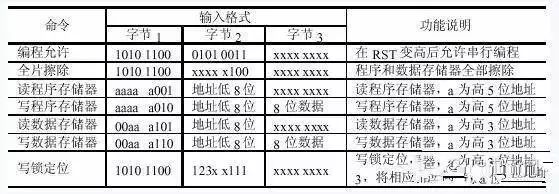
Table 1
(4) AT89S8252 serial programming timing diagram, AT89S8252 serial programming timing shown in Figure 1.
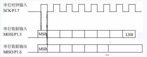
figure 1
4 hardware design
1 Connect to the SPI port of the MCU through the parallel port of the computer;
2 In order to protect the computer parallel port, it is necessary to add one 74HC244 as the isolation.
A practical schematic is shown in Figure 2. (It has been tested and can be used with confidence.)
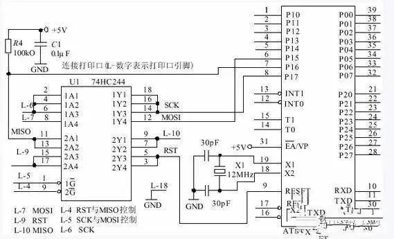
figure 2
5 Parallel control with VB programming
The base address of the print port is typically 0x278, 0x378, or 0x3BC, which can be found in the control panel. For the convenience of the reader, Table 2 lists the descriptions of commonly used print port pins and register bits.

Table 2
The most easy-to-learn language in the Windows environment is probably not VB, so our development tools also use VB as the programming language. However, due to the protection of Windows, VB cannot directly read and write the print port, so we need another program module to directly read and write the print port. Many of these modules can be found on the Internet and quite a few modules are free to use.
After trial, I recommend Winio v2.0.
The module supports Win9X/NT/2000/XP (http:// Yariv Kaplan) with detailed help, example programs and source code. When using, copy the four files Winio.sys, Winio.dll, Winio.vxd and Winio.bas to the working directory, and add the Winio.bas module directly in VB. There are four functions used in this example, which are explained below.
1 IniTIalize(): Allows port control functions. Called once before using the port input and output function, successfully returns "1", failure returns "0".
2 Shutdown(): Close the port control function. Execute once when exiting the program, returning "1" successfully, and returning "0" if it fails.
3 GetPortVal(ByVal PortAddr As Integer, ByRef Portval As Long, ByVal bSize As Byte) As Boolean: Read port function, PortAddr is the port address, Portval is the port value, bSize is the number of bytes to read. Returns "1" when the read succeeds and "0" if it fails.
4 SetPortVal(ByVal PortAddr As Integer, ByVal Portval As Long, ByVal bSize As Byte) As Boolean: Write port function. PortAddr is the port address, Portval is the value to be written, and bSize is the number of bytes to write. A successful write returns "1" and a failure returns "0".
The declaration of the four functions in the Winio.bas module is as follows:
Declare FuncTIon IniTIalizeWinIo Lib “WinIo.dll†() As Boolean
Declare FuncTIon ShutdownWinIo Lib “WinIo.dll†() As Boolean
Declare Function GetPortVal Lib "WinIo.dll" (ByVal PortAddr As Integer, ByRef Portval As Long, ByVal bSize As Byte) As Boolean
Declare Function SetPortVal Lib "WinIo.dll" (ByVal PortAddr As Integer, ByVal Portval As Long, ByVal bSize As Byte) As Boolean
6 Intel HEX format file
Since the files generated by the general compiling software for writing to the chip are all files in the Intel HEX format. Intel HEX files are text files that can be viewed in Notepad. A line of an Intel HEX file is called a record, and each record is composed of hexadecimal characters, and two characters represent the value of one byte. An Intel HEX file usually consists of several records, each of which has the following form:
:LLAAAATTDD. .DDCC
":" - the starting mark of the record;
LL - record length, indicating the number of data bytes in the record;
AAAA - the first address of the data load (16 bits);
TT - record type, 00 means data record, 01 means file end; (Note: some compiler software will generate record types larger than 01, this application ignores records larger than 01 record type.)
DD - data value (bytes);
CC - checksum. (Adding itself to all bytes in the record except the start flag should be 0, not 0 is wrong.)
Detailed description of VB programming can be found in the supplemental version of this journal (http://). (Because the flow of each subroutine is relatively simple, the source code is directly given, but the flow chart is not drawn. The program uses a bottom-to-top design method.)
Conclusion
Although the above program can implement various basic functions, it is not perfect, and does not consider various abnormal situations. The reader can improve according to the actual situation.
Because the price of AT89S8252 is still relatively expensive, it is difficult to buy on the market now, but Atmel's AT89S51/52, which replaces AT89C51/52, also has system programming function, and the price is cheap. The implementation of the system programming is similar to that of the AT89S8252. Some modifications can be made to some of the programs in this example to support the device. The "MCS51/AVR/PIC 3-in-1 Downloader" produced by the author adds support for the AT89S51/52.
Because the C language execution efficiency is lower than the assembly, it looks like a few lines of code, sometimes it takes a long time, so you must pay attention to this problem when using the open dog. This problem is easily overlooked when using the emulator, because even if the watchdog is reset in your program, the emulator (the Juyang emulator can turn on/mask this function) will often block the reset signal, so the program still Will work fine.
When you run the program and then run it, you can't run it properly until you find the program you just debugged. That's because your program has been resetting all the time. Note that you can't see the reset by using the oscilloscope to observe the RST pin. Signal because the watchdog reset does not affect the level of the RST pin.
In another case, there is no watchdog inside the chip, but there is a CPU monitor chip in the circuit. It is often able to provide a reset signal, and it is a reset signal for various reasons. If you find the above, you can use an oscilloscope. Check the RST pin to see if there is a level change.
Therefore, it is recommended that you use the CPU monitor chip when you are doing 51 product development. It is very easy to use the X5045, because it also has the Eprom function. This can be used in many occasions, and you can also use the dedicated reset chip such as MAX708. Stable and convenient.
1.ANTENK Flexible Printed Circuit (FPC) and Flexible Flat Cable (FFC) connectors are ZIF (zero insertion force) and LIF (low insertion force) connectors designed to provide a fast, easy, reliable method to make a connection of flexible printed circuits to a PCB. Adam Tech`s special contact design completely preserves conductor integrity by eliminating all wiping action while making connection. Flex circuitry enters the connector and the connector cap is pressed down to capture the flex circuit producing a stable, high pressure connection. Raising the cap releases the pressure for exchange or replacement of circuitry. This series includes single and dual row versions in thru-hole or SMT mounting in vertical or horizontal orientations.
2.Our products are widely used in electronic equipments,such as monitors ,electronic instruments,computer motherboards,program-controlled switchboards,LED,digital cameras,MP4 players,a variety of removable storage disks,cordless telephones,walkie-talkies,mobile phones,digital home appliances and electronic toys,high-speed train,aviation,communication station,Military and so on


FFC Connector Range Available as:
0.3,0.5, 0.8, 1.0,1.25, 2.54mm connector pitch
Surface mount
Side and Top entry
Side entry parts - Top and bottom contact options
ZIF (Zero Insertion Force)
Slide and flip lock actuator styles
Specifications:
Material And Finish:
Insulator: LCP
Lock: PPS
Insert Spring:Phosphor Bronze,
Matte Tin Plated
Solder Platten Area:Phosphor
Bronze,Matte Tin Plated
Voltage:500 V AC(rms)/DC
Current:0.5 A AC(rms)/DC
Contact Resistance:20 mΩ max(initial)
Insulation Resistance:800 MΩ min
Operating Temp:-20°-85°
Fpc Connector,Fpc Cable Connectors,Ffc Cable Connectors,Pitch Fpc Connector,Surface mount FPC/FFC Connectors,Top entry FFC Connectors, Side entry FFC Connectors
ShenZhen Antenk Electronics Co,Ltd , https://www.antenksocket.com