How to directly access the entire 4GB memory space in DOS real mode
As software developers, most of them are mysterious and difficult to understand for protection mode. In the process of developing 32-bit micro-kernel preemptive multi-threaded operating system, I deeply understand the address mechanism of the CPU. Here I will analyze the working principle of the CPU and unravel the mystery of the protection mode. The reader will find that the protection mode is actually The mode is as simple and easy to control. On this basis, use four or fifty lines of C language program to achieve the access protection mode and direct access to the entire 4GB memory space under real mode.
Although there are many books explaining the protection mode, none of them can be explained clearly and succinctly. The lengthy and cumbersome term makes people want to doze off, and there are even many protected mode test programs written by sinks (which may not work at all). In fact, the C language itself can be used to do the protection mode.
We may know that the CPU starts running from the BIOS in the ROM after power-on, while the Intel documentation says that the 80x86CUP is always powered up from the top 16 bytes of memory, so the BIOS is at the top 64K (FFFF0000H) or 1M of the memory. Under the 64K (F0000H)? In fact, both places appear at the same time (can be verified by the program that accesses 4GB of memory later).
Why? In order to figure out the above problem, first understand how the CPU handles the physical address? It is really in the real mode, the segment register is shifted to the left by 4 bits and the offset is added. In the protection mode, the segment descriptor is used. Is the base address plus the offset and the two are unrelated? The answer is that the two are actually the same. When Intel introduced the 80286, its address space became 24 bits. From 20 to 24 bits of the 8086, it is natural to increase the segment registers. In fact, they have all been increased, just because of protection. The larger part was not seen by the program. After 80386, the address was increased from 24 to 32 (the 80386SX is 24). The entire segment register is shown below:
@@12A08400.GIF; Figure 1@@
In the 8086, the CPU only has a "visible part" and thus directly participates in the address formation operation. However, after 80286, the address value is already included in the "invisible part", and the "visible part" degenerates to just one. The label no longer has to participate in the address formation operation. The formation of the address always extracts the base value from the "unseen portion" and adds the offset to form the address. That is to say, when a segment register is loaded with a value in real mode, the limit of the "invisible portion" is set to FFFFH, and the base portion is to be loaded with the value shifted to the left by 4 bits, and the attribute portion is set to 16 bits. 0 privilege level. This process is the same as loading a segment store in protected mode, except that the "invisible portion" of the protected mode is taken from the description table, and the real mode is a fixed set of processes.
For the CPU to form the address, there is no real mode and protection mode, it only uses the base address ("invisible part") to add the offset. The difference between real mode and protected mode is actually just to protect the processing component to work more accurately, such as not allowing the code segment to be written. The segment registration load in real mode has a fixed formation method and thus does not require a "descriptor" of the protection mode, thus maintaining compatibility with the 8086/8088. The "descriptor" is also set to load the "invisible portion" of the segment register.
From the "full segment register" above, it can be seen that the address formation of the CPU has nothing to do with the current value of the "visible part", which explains why the code behind is still running correctly when entering the protected mode. The value of the segment register CS is still the real mode value before entering the protection mode, or the program works normally before the code segment CS is changed from the protection mode back to the real mode, and does not "mutate" to the left shift of the CS by 4 bits. The address goes up. For example, in the protection mode, CS is the selector of 08H. When it is in the real mode, CS is still 08H but the address does not suddenly become 80H plus the amount of partial segment. Because the formation of the address ignores the current value of the "visible portion" of the segment register, this value is only useful to the CPU when it is loaded.
The formation of the address is independent of the operating mode of the CPU, which means that the real mode is exactly the same as the 0 privileged protection mode. Understand this mechanism, in real mode, it can handle things that are usually considered to be done only in protected mode, such as accessing the memory of the entire machine. You can ignore the many terms in protected mode, or it is easier to understand, such as the selector is the "visible part", the descriptor is set to load the "invisible part".
As a mechanism for verifying the CPU, a C program that accesses 4 GB of memory in real mode is written here. There are some books that also introduce assemblers that have the same functionality, but they all mistakenly believe that the design of the 80386 chip is missing. In fact, Intel itself uses this method, so that the first instruction can be started from FFFFFFF0H when the CPU is powered on. This technology is used every time after 286, every machine is cold start, but we don't know. . The CPU powers up and the entire code segment register looks like this:
@@12A08401.GIF; Figure 2@@
EIP=0000FFF0H
Thus CS:EIP forms the physical address of FFFFFFF0H. When the CPU performs a long jump and reloads into CS, the base address changes.
In order to access the 4G memory space, there must be a segment register with an "invisible portion" bounded at 4G-1 and a base address of 0, thus containing 4GB of memory, regardless of the value of the visible portion. Obviously it is impossible to have the segment registers load these values ​​directly in real mode. The only way is to let the CPU enter the protection mode for a while and then return to real mode immediately after loading the segment registers.
Entering the protection mode is very simple. As long as the GDT is set to set the bit 0 of the CRO register to 1, the CPU is in the protection mode. From the previous analysis of the CPU address formation mechanism, it is known that the "visible part" value of the register is ignored. Whether it is legal or not, the various segment registers are available as if they were not in protected mode. The real mode can be returned after loading a value containing a 4GB address space into a segment register.
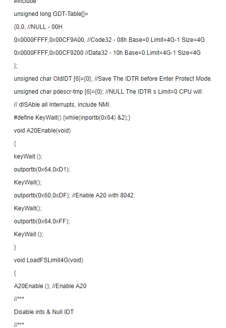
The GDT can be built in advance as follows:
Unsigned long GDT-Table[]={0,0, // null descriptor, must be zero 0x0000FFFF, 0xCF9A00, //32-bit flat code segment 0x0000FFFF, 0xCF9200 } , //32-bit flat data segment just for access For data, only two GDTs are sufficient, because there is no reloading of the code segment. Here are three GDTs for completeness.
Normally, all interrupts should be turned off when entering protection mode. Set the IDTR limit to 0. The CPU automatically turns off all interrupts, including NMI. After returning to real mode, the IDTR is restored and the interrupt is opened.
In addition, the control of the A20 address line is also important for proper access to the entire memory. Let the 8042 turn on the A20 address line before entering the protection mode.
In this example, the FS segment register is set to access the base address and boundary of 4GB of memory. Since there are very few programs in DOS that use GS, FS, two 386-increased segment registers, when reading and writing in the 4GB range. Any place can be reached by the FS segment until the FS is reloaded in real mode.
This example runs on 386SX, 386DX, 486. The example has a very detailed comment. Since this program is compiled with BC 3.1 and its connector cannot handle 32-bit registers for DOS programs, add the opcode prefix 0x66 and the address prefix 0x67 directly to the code. The 16-bit program in DOS real mode can use 32-bit registers and addresses. The equivalent 32-bit instruction is given as a comment on the right side of the program. Note that in the 16-bit instruction, the instruction code of mov al, byte ptr [BX] is exactly the 32-bit instruction mov al, byte ptr[EDI].
Readers can use this program to verify that the BIOS appears in both areas. If a linear addressing capability VESA display card (such as TVGA9440) can further verify the linear display buffer works above 1MB.
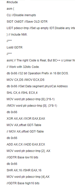
Db 0x66
SHR AX, 16 //SHR EAX,16
MOV word ptr pdescr-tmp [4], AX
//GDTR Base high16 bits
LGDT pdescr-tmp //Load GDTR
}
//****
//* Enter 32 bit Flat Protected Mode
//****
Asm{
Mov DX, 0x10 // The Data32 Selector
Db 0x66, 0x0F, 0x20, 0xC0 // MOV EAX, CR0
Db 0x66
MOV BX, AX // MOV EBX, EAX
OR AX, 1
Db 0x66, 0x0F, 0x22, 0xC0
//MOV CRO, EAX // Set ProtecTIon enable bit
JMP Flsuh
} //Clear machine perform cache.
Flush: // Now In
High Density Mpo Mtp Cabling,Pre Terminated Cable For Data Center,Mpo-Lc 12F Aqua Hybrid Cable,Mpo To 4Lc Duplex Om4 Hybrid Cable
ShenZhen JunJin Technology Co.,Ltd , https://www.jjtcl.com