Power MOSFET in electric vehicle amplifier circuit structure and characteristics
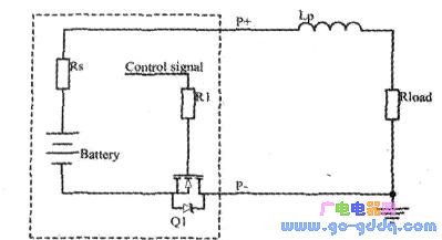
A simplified model of the discharge circuit of the lithium iron phosphate battery protection board for an electric bicycle is shown in the following figure. Q1 is a discharge tube using an N-channel enhancement MOSFET. In actual work, depending on the application, multiple power MOSFETs are used in parallel to reduce on-resistance and enhance heat dissipation. RS is the equivalent internal resistance of the battery. LP is the battery lead inductance.
During normal operation, the control signal controls the MOSFET to turn on, and the terminal P+ and P- output voltages of the battery pack are used for the load. At this time, the power MOSFET is always on, the power loss is only conduction loss, there is no switching loss, the total power loss of the power MOSFET is not high, and the temperature rise is small, so the power MOSFET can work safely.
However, when the load is short-circuited, the battery has a very high discharge capacity because the loop resistance is small, so the short-circuit current suddenly increases from several amps of several amps to several hundred amps. In this case, the power MOS-FET is easily damaged. .
Large Servo Drives,Digital Ac Servo Driver,Variable Frequency Drives,Full Closed Loop Servo Driver
Zhejiang Synmot Electrical Technology Co., Ltd , https://www.synmot-electrical.com