Pyroelectric infrared control circuit and application
The thermoelectric infrared detector has the advantages of sensitive detection, reliable operation, convenient installation, long control distance and large sensing angle. It has been widely used in systems such as anti-theft, alarm, remote sensing and automatic control. Due to different usage requirements, engineers and technicians often need to design their own amplification and control circuits, while the pyroelectric infrared sensor head (PIR) outputs a low signal frequency (about 0.1 Hz to 8 Hz close to direct current) and low energy (less than level). 1mV), so it is difficult to achieve satisfactory results, especially the contradiction between sensitivity and anti-interference. The YX7603 series thermoelectric infrared control lC recommended by us not only solves these problems properly, but also has the following characteristics:
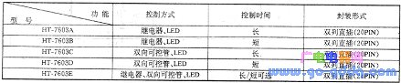
1. Excellent performance. The 7603E has three independent output circuits, which can respectively drive relays, bidirectional controllable tubes and light-emitting diodes. They can be used separately and can work together without interference, which greatly facilitates designers and users. The drive time of the relay and the bidirectional controllable tube can be flexibly selected. The 7603 series provides two different time ranges: Long (48 seconds to 15 36 seconds) and Short (4 seconds to 128 seconds). These outstanding advantages are other Integrated circuits and infrared thermoelectric modules are out of reach.
2. full functioning. The 7603 Series lC is a large-scale CMOS integrated circuit with low power consumption and high performance. It has: automatic light control function (daytime standby, nighttime power on), power-on delay function (automatic delay of 3~5 seconds for the operator to exit the control area), trigger delay function (check the alarm after 0.5 seconds, Reduce false triggering), gain adjustment function, power fast recovery function, test, reset function... Its circuit is so rich and the external components are so few, there are only a total of more than ten components (not including the power circuit). Therefore, it is easy to install and has a low failure rate. The functional block diagram of the integrated circuit is shown in the figure below.
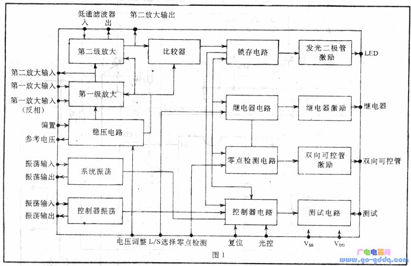
The 7603E is a thermoelectric infrared control circuit that integrates all of the above features. It is no exaggeration to say that an integrated circuit is a complete and fully functional control.
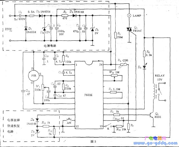
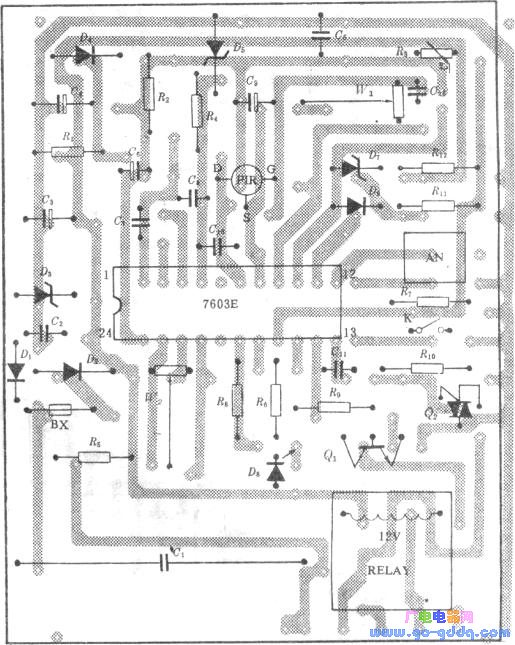
Brief description of the principle: Referring to the above figure, we can see that when the infrared radiation radiated by the moving object is taken up by the PIR (thermoelectric red sensor head), there is a weak signal input to the 7 pin of the 7603E. The integrated circuit has two levels of direct coupling inside. The low-frequency amplifiers have a total amplification of 3600 times. To make them work stably and reliably, the secondary amplifiers are powered by an internal voltage regulator, and a feedback resistor 设计 is designed on the external circuit of the first-stage amplifier to adjust the gain. To prevent self-excitation, the signal enters the comparator through the low-pass filter, and then is coupled to the relay, the bidirectional controllable tube, the control circuit of the LED, and the driving circuit. The three drive circuits have their own characteristics: the relay drive circuit has large output current, stable and reliable operation, and the suction time is continuously adjustable. The two-way controllable tube adopts zero-crossing trigger technology to eliminate the pollution of high-order harmonics to the power supply. The pass time is also continuously adjustable. The LED's drive output is a low-level pulse with a pulse width of 1 second, so it is a trigger indication. In actual use, we can use this pulse directly to control other devices without connecting the LED. The power failure fast recovery circuit can be disconnected, and has no obvious influence on the normal operation of the system. In order to reduce the size of the device and reduce the weight, the power supply part adopts the capacitive step-down technology, which is particularly convenient for the 7603C/D using the bidirectional controllable tube output. If the battery is used directly, the power supply part can be omitted. Of course, the transformer can be stepped down, rectified, and filtered to obtain DC power. Although the volume is larger, it is extremely advantageous for the operation of the relay. (Because the internal resistance of the capacitor is very large, improper selection of cl will cause the relay to work abnormally, or even the entire circuit is out of order). The figure below shows the component mounting diagram of the 7603E. Note that the grounding of the 7603E is achieved by the internal wiring of the button switch AN. If other switches are used (or not), don't forget to ground the Vss reliably.
Since the basic principles of the 7603A, B, C, and D are the same as those of the 7603E, only some functions are missing, so the principle is not repeated here. Their schematics are shown below.
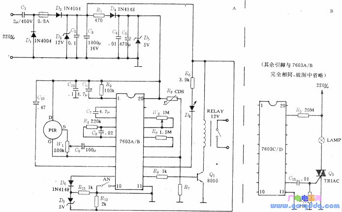
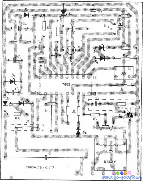
Printed circuit board A, B, c, D use one (below), because the output of 12 feet of f7603A, B is the relay (R9, Q1, RELAY in the figure) 7603C, the output of 12 of D is bidirectional Controllable tube (see the components in the dotted line in the figure), so if you choose different number, you only need to solder the relevant driving components.
In the 7603 series, the operating voltage of lC is 4v~5.5V, the typical value is 5v, and the limit value is 6V.
Debugging points: Because the capacitor is stepped down, the whole device is charged, and a 1:1 isolation transformer is added during the debugging process. If only the relay output is used, 11.5v DC can be directly introduced at both ends of C3 during debugging (not greater than 12V. Otherwise D3 will be burned). First adjust R7 so ​​that the CDS input of the integrated circuit is 3.5 volts during the day and 2.0 volts during the night. If no automatic light control is required, a resistor of about 1 kΩ can be soldered at R3, and R7 is still adjusted to make the CDS input. It is 2.0 volts. Then turn the sliding arm of w1 to the s end of PIR (the input signal is the largest), shake it by hand before PIR, then the LED should be on, and the relay (or bidirectional controllable tube) starts to work, after 1 second. The LED is off, and the relay (bidirectional controllable tube) is still working normally, and then released (cutoff) after a delay. To change the pull-in time, you can first select the L/S state (only 7603E), the low level is Short, the float is Lang, and the resistance of W2 is adjusted until it meets the usage requirements.
If the circuit is self-excited during the debugging process, the LED (relay, bidirectional controllable tube) will also flash periodically when there is no signal input. At this time, Rz can be adjusted separately (changing the bias of the first-stage amplifier). Small C7, C9 (changing low frequency response), reducing Rf (reducing gain), increasing C10 (suppressing oscillation), and eliminating self-excitation by the above debugging. Wl is used to control the detection distance. The test terminal is active low and grounding is prohibited during normal use. After debugging, the isolation transformer can be sprinkled and the Fresnel lens is put into use. The control distance of the device is 5-7 meters. To detect a longer distance, only one level must be added between PIR and 7603. amplifying circuit.
Component selection: C7 must use non-polar capacitors, R2 is recommended to use metal film resistors, W1 resistance can not be less than 250kΩ, if you do not need to adjust the sensitivity often, variable resistor W1 is recommended to use metal film resistors.
Application example: Since the 7603E has various control functions and output modes, it is designed for such as nighttime automatic lights, safety guard systems, fire monitoring devices... Just select the appropriate model IC and connect the control device. Here we introduce one with the 7603E. The automatic doorbell system is made, the block diagram is shown in the figure below.
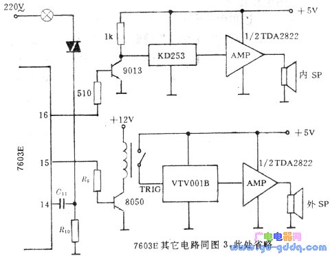
When someone comes, the system will politely address the guests: "Welcome, please wait a moment, I will open the door right away", and send a "å®å’š" call message to the room, every 10 seconds before opening the door. Repeat once, at the same time, the system will automatically turn on the lights. The solid recording part adopts VTVOO1B, the call information is directly omitted with the "å®å’š" doorbell music integration lC, the circuit diagram of the 7603E is omitted (refer to Figure 3), and W2 is adjusted so that the control time of 14#, 15# is 10 seconds. Interested readers can make a smart intercom and recording remote sensing doorbell by simply developing the block diagram of Figure 7.
Shaded Pole Motor,Shaded Pole Induction Motor,The Shaded Pole Motor,Shaded Pole Single Phase Motor
Hangzhou Jinjiu Electric Appliance Co Ltd. , https://www.jinjiufanmotor.com