Homemade high quality pocket FM FM stereo radio circuit diagram
It is easy to make a high-performance FM AM radio with TA2111F. The advantage of this IC is that the AFC circuit is integrated inside the IC, no external varactor is needed, only one external 5pF capacitor can be connected; the FM IF part is done. Instead of the middle week, the ceramic filter is replaced, which eliminates the debugging of the intermediate frequency; the stereo decoding part does not need to adjust the stereo pilot frequency of 19 kHz. It can be seen that assembling the FM radio with the TA2111F is very simple. So, what is the performance of the radio assembled with the TA2111F? The author has a self-made FM stereo radio with TA8127N. Compared with the radio assembled with TA2111F, the latter has more stations, less noise, and the stereo light is easy to light. The TA2111F is a flat package and the TA2111N is a dual in-line package.
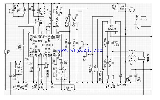
Figure 1 is a circuit diagram of the radio, and Figures 2 and 3 are printed circuit diagrams. Since the amplitude modulation band is not assembled in this unit, the {7}, {20}, and {24} pins of the IC are not used. The {16} pin is the band switching pin, and the C6 short circuit can be converted to the AM band. Shorting C8 turns the FM stereo to mono.
The machine uses the lead of the stereo earphone as the antenna. The FM signal is input from the {1} pin of TA2111F through the bandpass filter composed of L4, C19, C18 and C16. According to the TA2111F pin name, the signal flow can be known. The {13}, {14} pin output is amplified by the low-power bi-amplifier TDA2822 to push the stereo headphones.
Component selection: The variable capacitor is a 4-connected capacitor, and the two-connected capacity for FM is equal to 4 to 24 pF. L1 is wound 3.5 turns on a 5 mm round bar with a 1 mm enameled wire. L2 is wound 3.5 turns on a 4 mm round bar with a 0.7 mm enameled wire. After L1 and L2 are mounted on the circuit board, a small sponge is inserted into the coil, and some molten paraffin is added to the coil and the sponge to prevent machine vibration. L4 is lapped on the ∮4.5mm round bar with 5 turns of ∮ 0.7mm enameled wire. L3 is an FM frequency discrimination coil. The potentiometer uses a miniature double-connected potentiometer.
Debugging: After the assembly is completed, turn on the power, turn on the volume, and rotate the variable capacitor. If you can receive the broadcast of several stations, the installation is correct. Then follow the steps below to debug.
1. Adjust the receiving range of the audio frequency to 88 ~ 108MHz, first turn the variable capacitor clockwise to the bottom, use a screwdriver to mobilize the fine-tuning capacitor of the oscillation, so that the radio receives a station with a frequency of about 108MHz; then turn the variable capacitor back to the bottom. Use the toothpick to turn the coil L2 and change the distance between the turns of the coil so that the radio receives a station with a frequency of about 88 MHz. Repeat this adjustment several times until the radio can receive stations near 88MHz and 108MHz.
2. Increase the low-end sensitivity: first turn the variable capacitor to near 106MHz, use a screwdriver to rotate the fine-tuning capacitor of the antenna until the rustling in the speaker is maximum; then turn the variable capacitor to near 92MHz, and use the toothpick to turn the coil L1. Change the distance between the turns of the coil until the rustling in the speaker is maximum, so repeat it several times.
3. Frequency adjustment: Use a screwdriver to adjust the magnetic cap of L3 to minimize the rustling in the speaker.
Coaxial Cable RG59 RG6
Conductor: Bare copper or Copper Clad Steel (Solid)
Insulation: Foamed PE
Shield: Aluminum/PET-Foil Bonded
Sheath: PVC (Polyvinyl Chloride)
Applications: Those Coaxial Cables are suitable for Digital, Analog, CATV, Satellite, Off-Air, Broadband
Coaxial Cable, Digital Coaxial Cable, RG59, RG6, CCTV Cable
Shenzhen Bendakang Cables Holding Co., Ltd , https://www.bdkcables.com