Wireless current detection micropower zero-drift operational amplifier knowledge sharing
Many current-sense circuits follow the same simple method: generating a voltage drop across the sense resistor: amplifying the voltage, reading it with an ADC, and then knowing the magnitude of the current. However, if the voltage at which the sense resistor is placed is quite different from the system, then things can quickly become complicated. A typical solution eliminates voltage differences in the analog or digital domain. However, there is a different approach here, using wireless.
The high side current sense amplifier operates in the analog domain. These ICs are compact, but the voltage difference they can withstand is limited by the semiconductor process. Devices rated above 100V are rare. Moreover, the accuracy of such circuits often decreases if the common mode voltage of the sense resistor changes rapidly or swings above and below system ground.
Magnetic or optical isolators often destroy the isolation barrier of the digital domain. The hardware may be more cumbersome, but it does not lose accuracy when working, and can typically withstand thousands of volts. This type of circuit requires an isolated power supply, but this power supply can sometimes be integrated into the isolator assembly. If the sense resistor is physically separated from the main system, then a long wire or cable may be required.
The recent emergence of low power signal conditioning and wireless technology provides a new approach. By allowing the entire circuit to float with the common-mode voltage of the sense resistor and wirelessly transmitting the measured data over the air, the voltage limit does not exist. The sense resistor can be placed anywhere without the need for a cable. If the power of the circuit is very low, then even an isolated power supply is not required, and it can be operated for many years with a small battery.
Wireless current detection
The current sense circuit shown in Figure 1 utilizes the LTC2063 chopper-stabilized op amp to amplify the voltage drop across the sense resistor. The AD7988 micropower SAR ADC digitizes the voltage drop and reports the results via the SPI interface. LTP5901 - IPM is a wireless module that automatically forms an IP-based mesh network with other nearby nodes. The device also has a built-in microprocessor to read the AD7988 ADC SPI port. The LTC3335 is a nanopower buck-boost regulator that converts the battery voltage to a constant output voltage. The LTC3335 also includes a coulomb counter to report the amount of charge drawn from the battery. Â Â Â Â Â Â Â Â
      Â
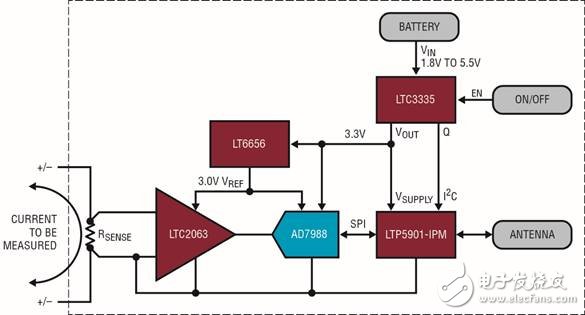
Figure 1: A low-power wireless current-sense circuit consisting of a low-power chopper-type op amp that amplifies the sense voltage, digitized with a low-power ADC and reference, and connected to a SmartMesh IPTM wireless module. A low power DC/DC converter regulates the battery and tracks the amount of power drawn from the battery.
Micropower Zero-Drift Operational Amplifier
To minimize the amount of heat generated in the sense resistor, the voltage drop is typically limited to 10mV to 100mV. Measuring this range of voltages requires input circuits with very low offset errors, such as zero-drift op amps. The LTC2063 is an ultra low power, chopper-stabilized op amp with a maximum supply current of 2μA. Since the offset voltage is below 10μV, the device can measure very small voltage drops without loss of accuracy. Figure 2 shows the LTC2063 configured to amplify and level shift the voltage across a 10mΩ sense resistor. Select the appropriate gain to map the ±10mV full-scale voltage on the sense resistor (corresponding to ±1A current) to a near full scale range on the output (centered at the intermediate supply). This amplified signal is fed into a 16-bit SAR ADC. The AD7988 was chosen because of its very low standby current and good DC accuracy. At low sample rates, the ADC automatically shuts down between conversions, resulting in an average current consumption as low as 10μA at 1ksps. The LT6656 voltage reference consumes less than 1μA and biases the amplifier, level shift resistor, and ADC's reference input.

Figure 2: The current sense circuit floats with the sense resistor voltage. The LTC2063 chopper op amp amplifies the sense voltage and applies an intermediate supply rail bias for the AD7988 ADC. LT6656 - 3 provide precise 3V reference.
Industrial strength wireless grid
SmartMesh wireless modules such as the LTP5901 - IPM include radio transceivers, embedded microprocessors and networking software. When multiple SmartMesh nodes are powered up near a network manager, these nodes automatically identify each other and form a wireless mesh network. All nodes in a network automatically implement time synchronization, which means that each radio transceiver powers up only during very short, specific time intervals. Thus, each node can act as a source of sensor information and a routing node for forwarding data from other nodes to the manager. This creates a highly reliable low power mesh network in which multiple paths are provided from each node to the manager, although all nodes (including routing nodes) rely on very low power operation.
LTP5901 - IPM includes an ARM Cortex - M3 microprocessor core running network software. In addition, users can write application firmware to perform tasks specific to the user application. In this example, the microprocessor in the LTP5901 - IPM reads the SPI port of the current measurement ADC (AD7988) and reads the I2C port of the Coulomb counter (LTC3335). The microprocessor can also place the chopper op amp (LTC2063) in shutdown mode to further reduce its current consumption from 2μA to 200nA. This further saves power in a very long use mode between measurements.
Nanopower coulomb counter
For measurement circuits, a typical power consumption reported by one node per second is less than 5μA, while the power consumption of a radio transceiver can reach 40μA. In fact, power consumption depends on various factors, such as how often the signal link takes a reading and how the node is configured in the network.
The circuit shown in this article is powered by two alkaline main batteries. The battery input voltage is regulated by the LTC3335 nanopower buck-boost converter with integrated coulomb counter. The converter provides a stable 3.3V output from a 1.8V to 5.5V input supply. Depending on whether the radio transceiver is in active mode or in sleep mode, the load current of a duty cycle wireless application may vary from 1μA to 20mA. The LTC3335 has a quiescent current of only 680nA at no load, which keeps the entire circuit at very low power when the radio transceiver and signal link are in sleep mode. In addition, the LTC3335 can output up to 50mA, which provides enough power for radio transmission/acceptance and for various signal link circuits.
In high-reliability wireless sensor applications, the use of photocell power is absolutely unacceptable. At the same time, replacing the battery too often can result in undesired costs and downtime. As a result, there is a need for a circuit that can accurately measure battery power consumption. The LTC3335 has a built-in coulomb counter. Whenever the regulator is turned on, it tracks the total amount of power drawn from the battery. This information can be read using the I2C interface and can then be used to predict battery replacement time.
to sum up
Linear Technology's combination of ADI's signal chain, power management and wireless networking products enables true wireless current sensing circuit design. Figure 3 shows an example. The new ultra-low power LTC2063 chopper-type op amp accurately reads out the small voltage drop across the sense resistor. The entire circuit, including the micropower ADC and voltage reference, floats with the common-mode voltage of the sense resistor. The nanopower LTC3335 converter can power the circuit for many years with a small battery while reporting the cumulative battery usage using its built-in coulomb counter. The LTP5901 - IPM Wireless Module manages the entire application and automatically connects to a highly reliable SmartMesh IP network.
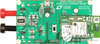
Figure 3: A complete wireless current-sense circuit implemented on a small board. The only physical connection is the banana jack used to measure current. The wireless module is shown on the right. The circuit is powered by two AAA batteries connected to the back of the board.
The air defense loudspeaker is applied to the civil air defense alarm system of many large civil air defense projects all over the country. Aluminum loudspeakers are widely applied to various fields such as water conservancy project, flood control and forewarning system, weather forecast and monitoring system , village radio and television project, etc.If you are interested in this product, feel free to contact us

Air-Raid Sirens,Air Defense Siren Speaker,civil Defense Siren Speaker,civil Defense alarm,Civil Defense siren
Taixing Minsheng Electronic Co.,Ltd. , https://www.ms-speakers.com