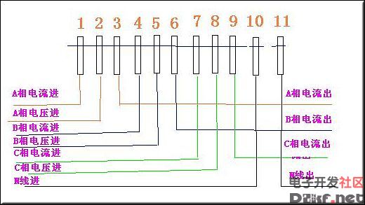
Three-phase four-wire electric meter wiring diagram
Turn over the terminal cover and you will see the wiring diagram of the three-phase four-wire meter. 1, 4, 7 are connected to the secondary side S1 end of the current transformer, that is, the current incoming end; 3, 6, and 9 are connected to the secondary side S2 end of the current transformer, that is, the current outgoing end; 2, 5, and 8 respectively Phase power; 10, 11 is the zero terminal. For safety, the current transformer S2 should be connected and grounded. Note that the current measurement samples of each current transformer must be in phase with their voltage samples, that is, 1, 2, and 3 are a group; 4, 5, and 6 are a group; and 7, 8, and 9 are a group.
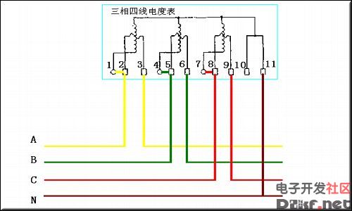
Three-phase four-wire electric meter wiring diagram without current transformer
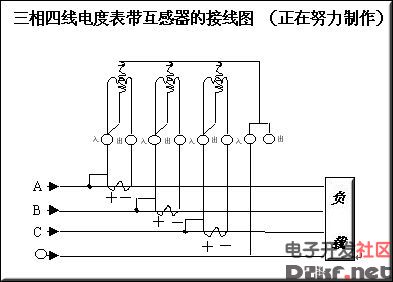
Three-phase four-wire electric meter wiring diagram with current transformer
Wiring diagram of three-phase four-wire meter with transformer
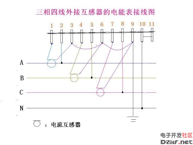
Wiring diagram of three-phase four-wire external transformer
Wall Switch Panel,3 Gang Switch Panel,2 Gang Switch Panel,Smart Light Switch Panel
Wenzhou Niuniu Electric Co., Ltd. , https://www.anmuxisocket.com