Machine vision electronic circuit design atlas - circuit diagram reading every day (82)
Linear LED driver circuit design strategy for TOP1 signal lamp
Circuit Description: This application note describes a linear LED driver scheme for driving six strings of LEDs, each containing four LEDs in series. Each string of LED loads has separate anode contacts with the cathodes connected together. The circuit is powered by a car battery with a minimum voltage of 10V and a maximum voltage of 28V, which provides 350mA per string of LEDs. Due to the common cathode architecture, the current-sense resistor must be placed at the anode end of the LED string. The maximum common-mode voltage at the current sense input of the LED driver (MAX16836) is limited to 4V. Therefore, the voltage across the sense resistor must be level-shifted to ground to match the driver requirements. A pair of PNP transistors convert the voltage of the LED sense resistor to a GND-referenced voltage and feed it to the MAX16836 current sense pin. The following equation provides calculations for R1, R2, R3, and R4 (part of the U1 in the circuit diagram).
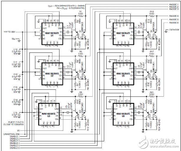
Figure 1. Driver design schematic
When the voltage of the LED string is at a minimum (7.6V) and the input voltage is at its maximum (28V), the LED driver circuit consumes the most power, greater than 7W. It is difficult to dissipate such a large amount of heat only through the heat dissipation of the board. Therefore, at high input voltages, the low duty ratio (down to 25%) dimming signal must be used to drive the UNIVERSAL DIM input to reduce the power consumption of the driver. .
Interpretation of NCV70522 Automotive Adaptive Headlamp System Circuit
Due to mechanical limitations, stepper motors can sometimes stall during adaptive headlamp system (AFS) applications. Once the motor is stalled, the electronic control unit (ECU) will lose track of the headlamp position and react inappropriately, creating a very serious safety problem, so stall detection is essential in AFS applications. It is usually possible to judge whether the motor is blocked or not by the back electromotive force (BEMF) of the motor. BEMF varies depending on motor speed, load and supply voltage. The traditional stepper motor driver chip has no BEMF output, but includes a built-in stall detection algorithm. The customer can only set a fixed stall determination threshold in the register, which means that under real road conditions all settings must be “offline†preset before work, and cannot be adapted to real working conditions. The NCV70522 microstepping stepper motor driver provides BEMF output through the SLA pin, which means it can perform stall detection calculations in real time and adjust the detection level according to different conditions.
The NCV70522 is a microstepping stepper motor driver for bipolar stepper motors. The chip is connected to an external microcontroller via an I/O pin and an SPI interface. The NCV70522 has a variety of output currents. It rotates the next microstep based on the pulse signal on the “NXT†input pin and the state of the direction register [DIRCTRL] or “DIR†input pin. The device provides subdivision from full steps to 32 microsteps and seven step modes selected by the SPI registers SM[2:0]. The NCV70522 contains the output of the SLA and can be used for stall detection algorithms and to adjust torque and speed calculations based on the BEMF of the motor. A typical application circuit diagram is shown.
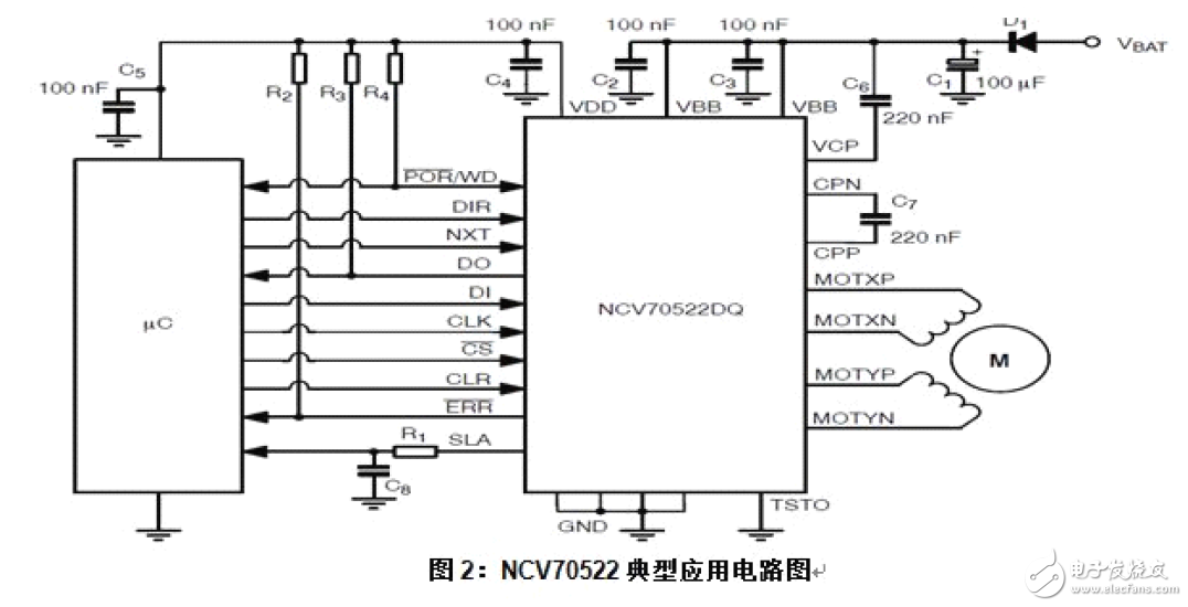
When the system is powered up, the microcontroller is initialized and the NCV70522 is reset. When these actions are completed, the coil current and step mode will be set. Then the motor drive will be enabled. The NXT pulse will be sent to implement the rotating motor. The motor speed is equal to the value of the NXT pulse frequency multiplied by the step subdivision mode.
------------------------------
Machine vision technology data collection -
Induction cooker relay, is a common device in the automatic control system, generally used to connect and disconnect the circuit, is an important part of the automatic control and remote control circuit.
Induction Cooker Relay,Digital Display Induction Cooker Relay,General Purpose Induction Cooker Relay,Miniature Induction Cooker Relay
Ningbo Xingchuangzhi Electric Appliance Co.,Ltd. , https://www.xingchuangzhi.com