Explain the difference between FIR filter and IIR filter
Digital filters are widely used in hardware circuit design. They are especially common in discrete systems. They can be divided into FIR filters and IIR filters. What are the differences and connections between them?
FIR filterdefinition:
The FIR filter is a finite-length unit impulse response filter, also known as a non-recursive filter. It is the most basic component in a digital signal processing system. It can guarantee arbitrary amplitude-frequency characteristics while having strict linear phase-frequency characteristics. At the same time, its unit sampling response is finite, so the filter is a stable system.
Features:
· The most important feature of the FIR filter is that there is no feedback loop and the stability is strong, so there is no instability problem;
· FIR has a strict linear phase, and the amplitude characteristics are arbitrarily set to ensure accurate linear phase;
· FIR design is linear and hardware is easy to implement;
· FIR vs. IIR filter, the same performance index, the order is higher, the performance of the CPU is higher.
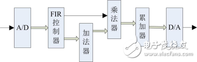
Figure 1 FIR filter schematic
IIR filterdefinition:
The IIR filter is an infinite impulse response filter, also known as a recursive filter, which has a feedback loop on the structure.
Features:
· The system function of the IIR digital filter can be written in the form of a closed function with a feedback loop;
· The phase nonlinearity of the IIR digital filter, the phase characteristics are not well controlled, and vary with the cutoff frequency. When the phase requirement is high, a phase calibration network needs to be added;
· The IIR filter has a historical output to participate in the feedback, and achieves better filtering effects at the same order as the FIR;
· The IIR digital filter adopts a recursive structure. Due to the rounding process in the operation, the error accumulates and sometimes a weak parasitic oscillation occurs.
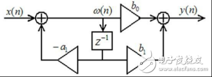
Figure 2 IIR basic schematic
the difference· Stability: Since the FIR filter has no feedback loop, the stability is stronger than the IIR;
· Phase characteristics: FIR is linear phase delay and IIR is nonlinear phase delay.
As shown in the figure below, it is a 10Hz square wave signal with a sampling rate of 1KHz.
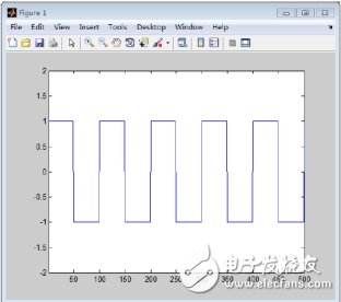
Figure 3 square wave signal
After the FIR filter, the filtered effect is shown in the figure below.
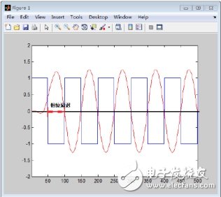
Figure 4 FIR filter effect diagram
After the IIR filter, the filtered effect is shown in the figure below.
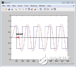
Figure 5 IIR filter effect diagram
It is not difficult to find through comparison that the IIR filter has a nonlinear phase delay. The correction requires bidirectional filtering for correction, which is difficult to control. The FIR filter is linearly delayed and can be directly corrected by left and right translation. The error is small.
· Signal processing speed: The filtered output of FIR depends on the current input data and historical input data. The filtered output of IIR depends on the current input data, historical input data and historical output data. Taking the digital filter based on FPGA hardware as an example, the FIR does not need to wait for the filtered output of the previous signal when processing the signal, and only needs to consider the input data to filter in real time; the IIR needs to wait for the filtered output of the previous signal, and there is a certain time. Delay, so there is no FIR fast in processing speed.
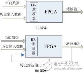
Figure 6 FIR and IIR filter comparison chart
From the above simple comparison, we can see that the IIR and FIR filters have their own strengths, so in practical applications, we should choose from many aspects. From the point of view of the use requirements, in the case of insensitivity to phase requirements, such as language communication, it is more appropriate to use IIR, so that it can fully utilize its cost-effective features; for image signal processing, data transmission and other systems that carry information by waveform, The linear phase requirement is higher, and the FIR filter is better. Of course, more factors may be considered in practical applications.
The manufacturing standard of the European standard plug (two rounds) is carried out according to the CE standard. European standard plugs are used in most European countries such as Germany, Austria, Holland, Sweden, Norway, Finland, and Russia. Since this standard is widely used throughout Europe, we call it the "Continental European" standard. The plug is two cylinders with a span of 19mm. The grounding level is completed by grounding the plugs on both sides. Central and Eastern Europe 7/7 European plugs have embedded pins, similar to French and Belgian sockets. The electrical parameter of the European standard socket is 10A-16A 230ACV AC power supply. The European standard socket is the safe socket in the world. The special grounding is mainly for the safety of people. Therefore, it is also the most widely used plug standard in the world. Note: The Italian standard plug has three cylinders and one wire, and the Danish and Swiss standard plugs have three cylinders into a triangle shape, and both have direct grounding pins.
Uk Plug Adapter,Europe Plug Type,Europe Electric Plug,Plug Converter Eu To Uk
Guangdong Kaihua Electric Appliance Co., Ltd. , https://www.kaihuacable.com